Steel wire rope locking device

A technology of locking device and steel wire rope, which is applied in the direction of wire tensioning appliances and manufacturing tools, can solve the problems of easy deformation, difficult operation of steel wire rope, high requirements, etc., and achieve the effect of not easy to trip, ingenious mechanism design, and weight reduction

Pending Publication Date: 2022-03-04
GUANGXI POWER GRID CO LIUZHOU POWER SUPPLY BUREAU
View PDF0 Cites 1 Cited by
  • Summary
  • Abstract
  • Description
  • Claims
  • Application Information

AI Technical Summary

Problems solved by technology

[0007] In view of the above deficiencies, the present invention provides a wire rope locking device, which can solve the existing problems of difficult operation, easy deformation, and high requirements when locking the wire rope.

Method used


Image

  • Steel wire rope locking device
  • Steel wire rope locking device
  • Steel wire rope locking device

Examples


Embodiment 1

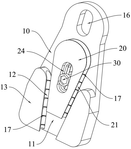
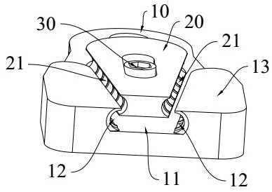
[0037] Please refer to figure 1 and figure 2 , A preferred embodiment of the present invention provides a wire rope locking device. The wire rope locking device mainly includes a connecting plate 10 and a wedge 20 slidably installed on the connecting plate 10. Both the connecting plate 10 and the wedge 20 are made of aluminum alloy, which meet the strength requirements of the device while reducing the weight as much as possible.

[0038] In this preferred embodiment, please refer to Figure 1 to Figure 4 , the side of the connecting plate 10 is provided with a raised portion 13, the raised portion 13 roughly occupies half of the side of the connecting plate 10, the raised portion 13 is provided with a wedge-shaped groove 11, the wedge-shaped groove 11 is wedge-shaped as a whole, and both ends are open, That is to say, there are two openings, one large and one small. A wedge 20 is matched and inserted in the wedge-shaped groove 11, and the shape of the wedge 20 is similar t...

Embodiment 2

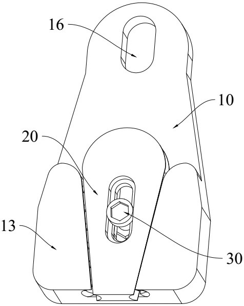
[0049] Please refer to Figure 6 , different from Embodiment 1, in this preferred embodiment, when the extension direction of the third elongated hole 16 and the wedge 20 are inserted in the wedge-shaped groove 11, the first groove 12 and the second groove on the same side One of the two long and narrow spaces formed by 21 extends in the same direction. Through this structure, during implementation, the tensioned part of the wire rope is consistent with the length direction of the third elongated hole 16, so that when tensioned, the length of the wire rope The direction is consistent with the extension direction of the long and narrow space formed by the first groove 12 and the second groove 21 where it is located, and the port of the first groove 12 will not squeeze the wire rope, thereby avoiding damage due to extrusion there. The steel wire rope guarantees the service life of the steel wire rope.


PUM


Abstract

The steel wire rope locking device comprises a connecting plate, a wedge-shaped groove is formed in the side face of the connecting plate, a wedge is inserted into the wedge-shaped groove in a matched mode, the two ends of the wedge-shaped groove are open, first grooves are formed in the side walls of the two sides of the wedge-shaped groove respectively, and second grooves are formed in the side faces of the two sides of the wedge respectively. And when the wedge is inserted into the wedge-shaped groove, the first groove and the second groove on the same side are oppositely arranged. The steel wire rope locking device provided by the invention is convenient to adapt to quick operation of locking a temporary stay wire of a line, is convenient to operate, high in efficiency and high in universality, and can quickly assist field maintenance personnel in quickly locking a steel wire rope.

Description

technical field [0001] The invention relates to the technical field of electric equipment, in particular to a wire rope locking device. Background technique [0002] Steel wire ropes are often used in power transmission work, such as tower erection, wire traction, and replacement of guy wires. The length of the wire rope is different every time, and the locking of the wire rope is more difficult. The traditional method is to lock the wire rope with the back buckle method. Hold the ground anchor, then adjust the length of the wire rope, tighten the chain hoist (double hook), so that the wire rope is gradually stressed. The steel wire rope is locked by a back buckle method, which has the following disadvantages: [0003] 1. The wire rope buckle will be deformed after a long time of stress; [0004] 2. The steel wire rope with a larger diameter has greater toughness, and it is not easy to operate the back buckle; [0005] 3. The operation skills are high, and unskilled oper...

Claims


Application Information

Patent Timeline
Patent Type & Authority Applications(China)
IPC IPC(8): B21F9/00B25B25/00
CPCB21F9/002B25B25/00
Inventor 廖远利韦国益唐家宾阙朝建于肖杰王双喜姜钦云毕明超蓝崭峰梁春柳韦红伟胡仁杰零晓佳
Owner GUANGXI POWER GRID CO LIUZHOU POWER SUPPLY BUREAU
Why Eureka
Try Eureka