Cable sheath stripping device

A technology for sheath stripping and cable removal, which is applied in the direction of cable installation devices, cable installation, dismantling/armoured cable equipment, etc., can solve the problems of time-consuming and laborious, inconvenient to remove the sheath of the cable, and achieve easy recycling Effect

Pending Publication Date: 2022-03-01
SHENZHEN HENGLIDE IND
View PDF0 Cites 0 Cited by
  • Summary
  • Abstract
  • Description
  • Claims
  • Application Information

AI Technical Summary

Problems solved by technology

[0004] In view of the above-mentioned related technologies, the inventor believes that the manual separation of the skin and core is time-consuming and laborious, and it is not convenient for the staff to remove the outer skin of the cable.

Method used


Image

  • Cable sheath stripping device
  • Cable sheath stripping device
  • Cable sheath stripping device

Examples


Embodiment Construction

[0039] The following is attached Figure 1-6 The application is described in further detail.

[0040] The embodiment of the present application discloses a cable sheath stripping device.

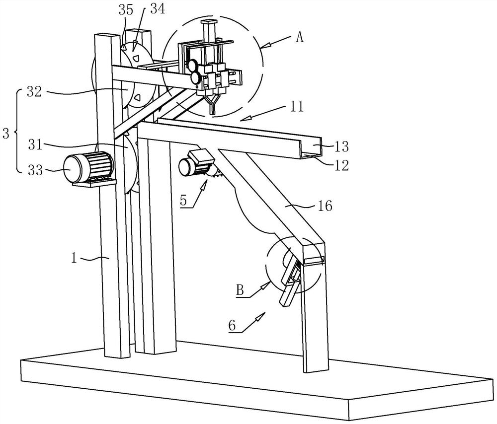
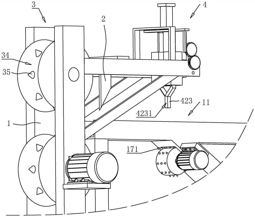
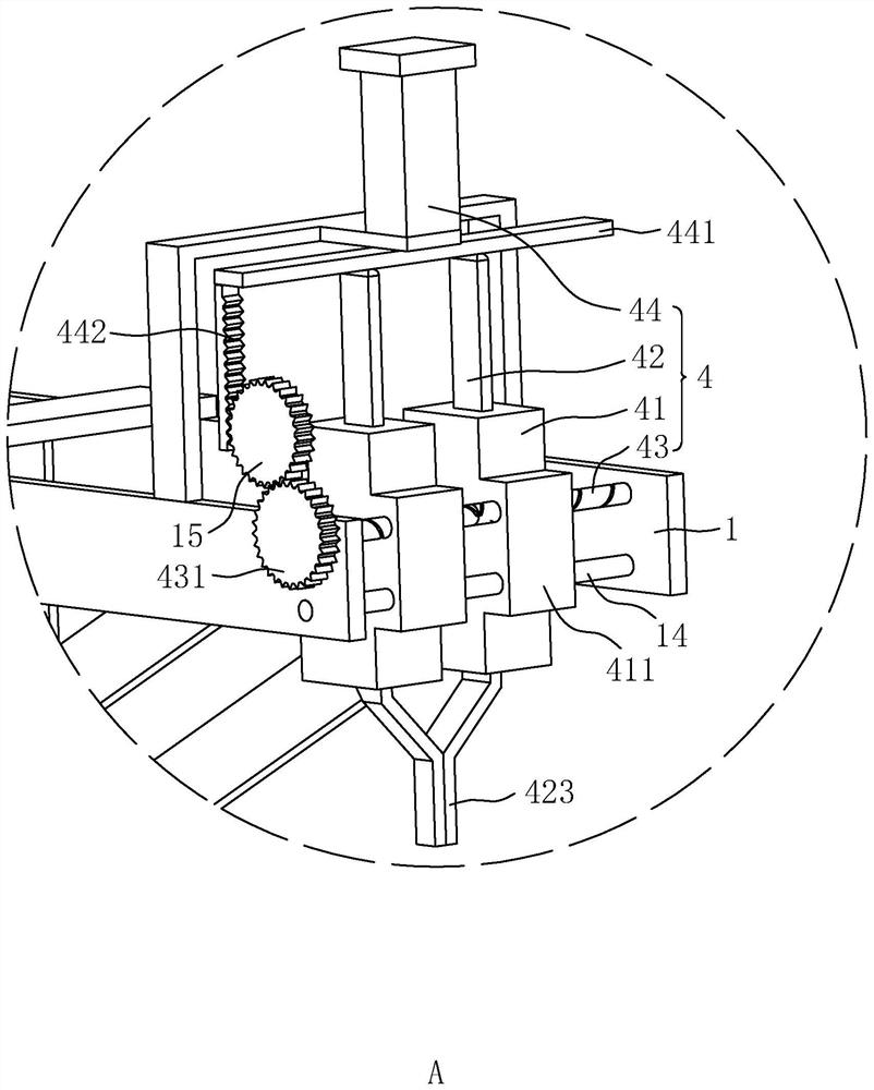
[0041] refer to figure 1 , figure 2 with image 3 , a cable sheath stripping device includes a frame 1, a cutting knife 2, a transmission assembly 3, a stripping assembly 4, a pulling assembly 5 and a cutting assembly 6.

[0042] refer to figure 1 with figure 2 , the frame 1 is provided with a cable space 11, the cable space 11 is used for cable movement, the length direction of the cable space 11 is consistent with the direction of cable movement; the frame 1 is fixedly connected with a rectangular strip A plate-shaped transmission plate 12, the transmission plate 12 is located below the cable space 11, the length direction of the transmission plate 12 is consistent with the length direction of the cable space 11, and the two sides of the transmission plate 12 are welded with strip-...


PUM


Abstract

The invention relates to a cable sheath stripping device, and relates to cable stripping, the cable sheath stripping device comprises a rack, a cable space is arranged in the rack, and the rack is fixedly connected with a cutting knife; a transfer assembly; the stripping assembly is arranged on the rack, and the stripping assembly comprises two sliding sleeves, two sliding rods, a two-way screw rod and a first driving cylinder; one sliding rod slides in one sliding sleeve, the sliding rods slide in the direction close to or away from the cable space, the sliding rods are elastically connected with the sliding sleeves, and the sliding rods tend to move in the direction away from the cable space under the elastic action; the sliding sleeves are slidably connected to the rack, the two sliding sleeves slide towards one side of the cable space, two threaded sections of the two-way screw are in threaded connection with the sliding sleeves respectively, a piston rod of the first driving cylinder is provided with an abutting plate, the abutting plate abuts against the two sliding rods at the same time, and the first driving cylinder is used for driving the sliding rods to slide. The cable stripping device has the effect of stripping the outer skin of the cable conveniently.

Description

technical field [0001] The present application relates to the field of cable stripping, in particular to a cable sheath stripping device. Background technique [0002] When recycling waste cables, it is necessary to perform stripping operation to separate the outer sheath and inner core of the cable, so as to realize the separate recycling of different parts of the cable. During operation, the staff will cut the outer sheath of the cable through a peeling machine. open. [0003] In the related art, the cable peeling machine can only cut the upper part of the outer rubber protective skin of the cable, and the outer skin of some cables will still be close to the inner core of the cable after the upper part is cut. Manual stripping is required to separate the cable sheath from the inner core. [0004] With regard to the related technologies mentioned above, the inventor believes that manual sheath-core separation is time-consuming and labor-intensive, and it is inconvenient f...

Claims


Application Information

Patent Timeline
Patent Type & Authority Applications(China)
IPC IPC(8): H02G1/12H01B15/00
CPCH02G1/126H02G1/1251H01B15/006Y02W30/82
Inventor 严碧鹏
Owner SHENZHEN HENGLIDE IND
Why Eureka
Try Eureka