Pressure relief device

A pressure relief device and pressure relief technology, applied in valve device, valve shell structure, structural parts and other directions, can solve the problems of rising internal pressure of the battery pack and affecting the normal use of the battery pack, etc.

Pending Publication Date: 2022-03-01
ILLINOIS TOOL WORKS INC
View PDF0 Cites 0 Cited by
  • Summary
  • Abstract
  • Description
  • Claims
  • Application Information

AI Technical Summary

Problems solved by technology

If the gas inside the battery pack is not discharged in time and accumulates in the battery pack, the pressure inside the battery pack will increase, affecting the normal use of the battery pack

Method used


Image

  • Pressure relief device
  • Pressure relief device
  • Pressure relief device

Examples


Embodiment Construction

[0025] Various embodiments of the present application will be described below with reference to the accompanying drawings, which form a part hereof. It should be understood that although directional terms such as "front", "rear", "upper", "lower", "left", "right", etc. are used in this application to describe various exemplary structural parts of this application and elements, but these terms are used herein for explanatory purposes only, based on the example orientations shown in the figures. Since the embodiments disclosed in this application can be arranged in different orientations, these directional terms are for illustration only and should not be regarded as limiting. Where possible, the same or similar reference numerals are used in this application to refer to the same components.

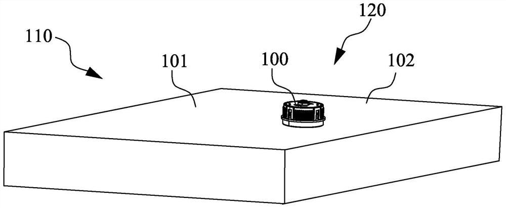
[0026] figure 1 is a schematic diagram of a battery pack 110 using the pressure relief device 100 according to the embodiment of the present application. Such as figure 1 As shown, the...


PUM


Abstract

A pressure relief device comprises a shell, a valve element and an elastic piece. The elastic piece is clamped between the shell and the top of the valve element, so that the valve element is provided with a first position and a second position. The valve element can move between a first position and a second position relative to the shell. In the first position, the valve element is supported by the shell, the bottom of the valve element covers the shell through hole, and the shell through hole can communicate with the shell containing cavity through the valve element through hole. And in the second position, the valve element leaves the shell so that a pressure relief channel can be formed between the bottom of the valve element and the shell, and the shell through hole can communicate with the shell containing cavity through the pressure relief channel. When the valve element moves to the second position from the first position, the elastic piece is compressed, and the reset elastic force of the elastic piece enables the valve element to move to the first position from the second position. According to the pressure relief device, the requirement of sealing performance detection of the battery pack provided with the pressure relief device can be met, and the function of concentrated pressure relief can be achieved under the condition that the structure of the pressure relief device is not damaged.

Description

technical field [0001] The present application relates to a pressure relief device, in particular, to a pressure relief device used in a battery pack. Background technique [0002] The battery generates heat during use, causing the temperature of the battery pack to rise. When the temperature inside the battery pack rises, the gas inside expands due to the heat. If the gas inside the battery pack is not discharged in time and accumulates in the battery pack, the pressure inside the battery pack will increase, affecting the normal use of the battery pack. Therefore, in order to ensure the safe use of the battery, it is often necessary to install a pressure relief device on the battery pack. When the pressure in the battery pack is higher than a predetermined value, the pressure relief device can be automatically opened to discharge the gas accumulated inside the battery pack and reduce the excessive pressure therein. Contents of the invention [0003] The purpose of this...

Claims


Application Information

Patent Timeline
IPC IPC(8): F16K17/06F16K17/164F16K27/02F16K37/00H01M50/325G01M3/02
CPCF16K17/06F16K17/0413F16K17/164F16K27/02F16K37/00G01M3/02
Inventor 何佳辉孙孟立
Owner ILLINOIS TOOL WORKS INC
Why Eureka
Try Eureka