
Electronic lock body

A technology for electronic locks and lock bodies, which can be used in building locks, non-mechanical transmission-operated locks, door/window accessories, etc. It can solve the problems that require a lot of force, and achieve the effect of saving effort in unlocking or locking

Pending Publication Date: 2022-03-01
中山市顺创智能科技有限公司
View PDF0 Cites 0 Cited by
  • Summary
  • Abstract
  • Description
  • Claims
  • Application Information

AI Technical Summary

Problems solved by technology

[0002] The electronic lock includes a square tongue assembly, a square tongue transmission device, a motor assembly, a PCB board, and a lock body control module. The PCB board is connected to the lock body control module, and the square tongue transmission device is connected to the square tongue assembly and the motor assembly. The signal of the lock body control module drives the motor assembly to act on the square tongue transmission device, so that the square tongue of the square tongue assembly protrudes or retracts into the lock body to achieve the purpose of locking or unlocking. In order to achieve the purpose of mechanical unlocking, electronic locks are generally equipped with There is a mechanical unlocking device, and the purpose of mechanical unlocking is achieved through a key. However, after the existing electronic lock is unlocked, the square tongue transmission device is still in a state of linkage with the square tongue assembly. At this time, if a key is used for mechanical unlocking, the key’s The rotation needs to drive the square tongue transmission device to rotate to realize the extension and locking of the square tongue. The entire locking process requires a lot of force. Therefore, there is a need for improvement in the existing structure.

Method used


Image

  • Electronic lock body
  • Electronic lock body
  • Electronic lock body

Examples


Embodiment Construction

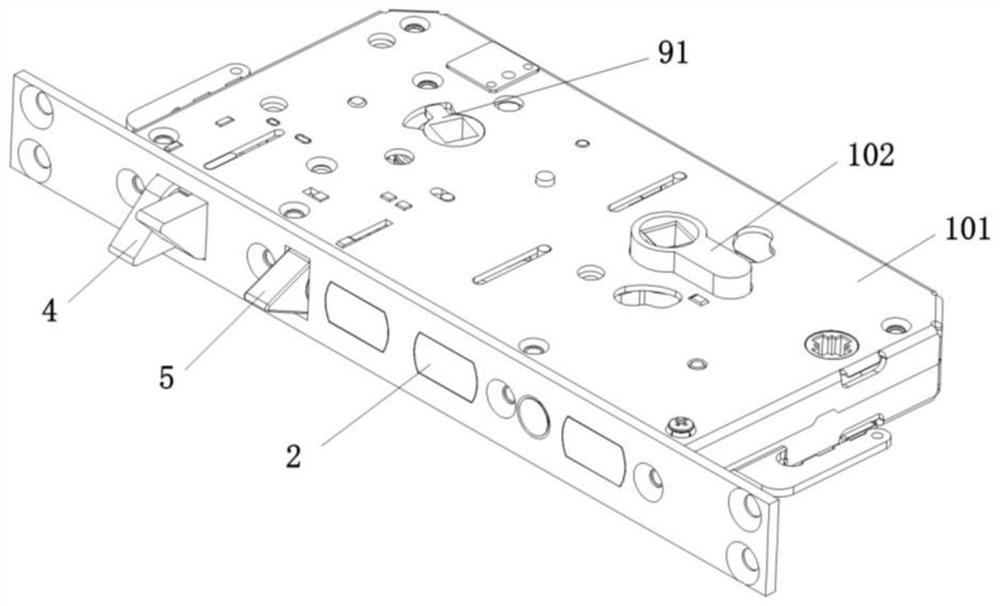
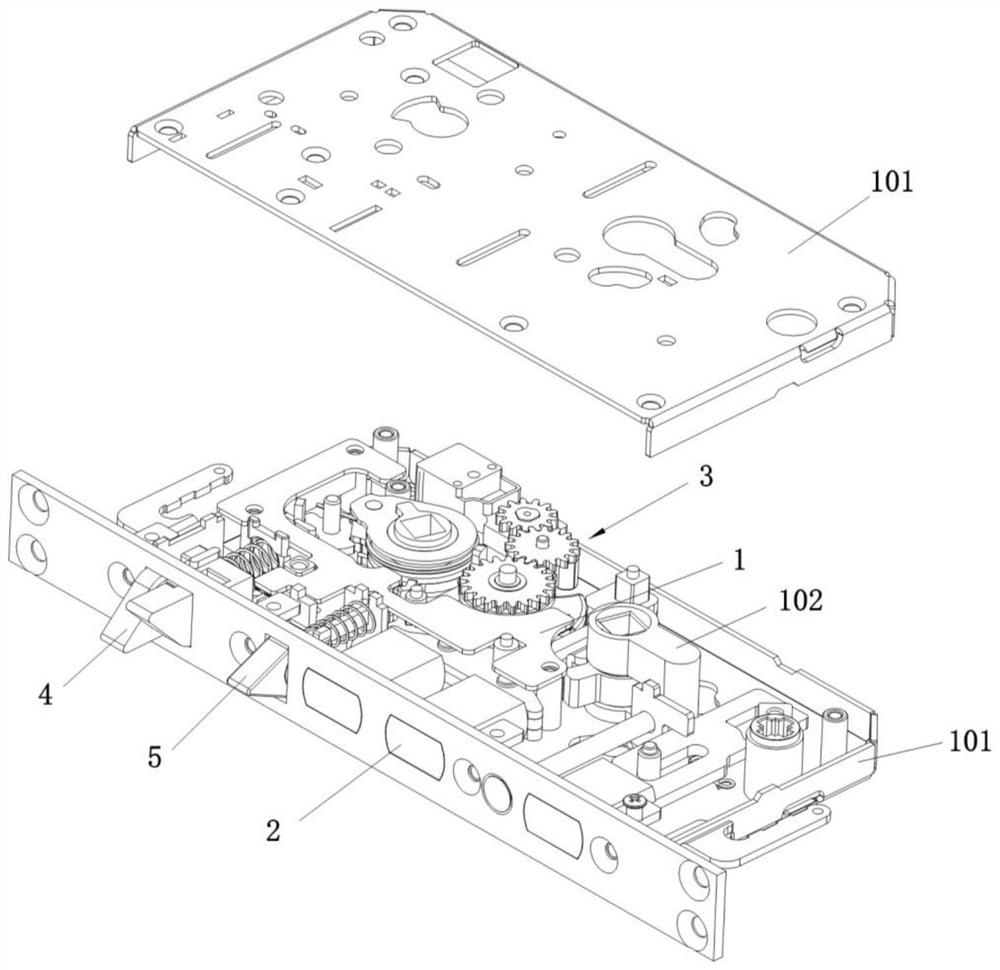
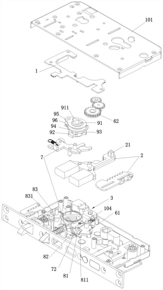
[0037] as attached figure 1 to attach Figure 4 As shown, an electronic lock body includes a lock case 101, a PCB board 1, a lock body control module, a square tongue assembly 2, a square tongue transmission device, a motor assembly 3, a lock cylinder 102, an oblique bolt assembly 4 and a triangular tongue assembly 5 The square tongue transmission acts on the square tongue assembly 2 to make the square tongue protrude or retract into the lock body (or lock housing 101) to realize the locking and unlocking functions of the lock body, and the lock core 102 is connected with the square tongue assembly 2.

[0038] as attached Figure 5 to attach Figure 8 As shown, the square tongue transmission device includes a pulling rod 61 and a motor gear 62 that are rotatably installed on the same first pivot shaft 103, and the motor gear 62 has an arc extending with the first pivot shaft 103 as the central axis. Arc groove 621; as attached Figure 9 And attached Figure 10 As shown, t...


PUM


Abstract

The invention relates to an electronic lock body which comprises a dead bolt assembly, a dead bolt transmission device, a motor assembly and a lock cylinder, the lock cylinder is connected with the dead bolt assembly, the dead bolt transmission device comprises a pulling rod and a motor gear, and an arc-shaped groove is formed in the motor gear; the pulling rod is provided with a pulling rod bulge; the motor gear is driven by the motor assembly, and the two ends of the arc-shaped groove act on the pulling rod protrusions respectively so that the dead bolt can stretch out of the lock body or retract into the lock body. After the dead bolt extends out of the lock body or retracts into the lock body, the motor gear rotates to a reset position, and the pulling rod protrusion slides along the arc-shaped groove in the process that the pulling rod of the lock cylinder pulls the dead bolt assembly to enable the dead bolt to extend out of the lock body or retract into the lock body. The lock cylinder has the advantages that the pulling rod protrusion slides along the arc-shaped groove and does not touch the two ends of the arc-shaped groove, so that in the mechanical unlocking process through the lock cylinder, the pulling rod does not drive the motor gear but idles relative to the motor gear, and unlocking or locking is quite labor-saving.

Description

technical field [0001] The invention relates to an electronic lock body. Background technique [0002] The electronic lock includes a square tongue assembly, a square tongue transmission device, a motor assembly, a PCB board, and a lock body control module. The PCB board is connected to the lock body control module, and the square tongue transmission device is connected to the square tongue assembly and the motor assembly. The signal of the lock body control module drives the motor assembly to act on the square tongue transmission device, so that the square tongue of the square tongue assembly protrudes or retracts into the lock body to achieve the purpose of locking or unlocking. In order to achieve the purpose of mechanical unlocking, electronic locks are generally equipped with There is a mechanical unlocking device, and the purpose of mechanical unlocking is achieved through a key. However, after the existing electronic lock is unlocked, the square tongue transmission de...

Claims


Application Information

Patent Timeline
IPC IPC(8): E05B47/00E05B63/14E05B15/00E05B3/00
CPCE05B47/0012E05B47/026E05B63/146E05B15/0013E05B3/00E05B2047/002
Inventor 赵宋桥陈俊坚
Owner 中山市顺创智能科技有限公司
Learn More