
Cast-in-place bridge formwork support system device and bridge cast-in-place rapid construction method

A technology of cast-in-place bridges and formwork, which is applied in the direction of bridges, bridge construction, erection/assembly of bridges, etc., can solve the problems of low construction efficiency, time-consuming and manpower, and achieve the effect of improving construction efficiency and reducing the possibility

Pending Publication Date: 2022-03-01
SHANDONG LUQIAO CONSTR
View PDF0 Cites 0 Cited by
  • Summary
  • Abstract
  • Description
  • Claims
  • Application Information

AI Technical Summary

Problems solved by technology

[0004] In view of the above-mentioned related technologies, the inventor believes that when pouring bridges in sections, the operator needs to remove the formwork support in the previous section, and then transfer the dismantled formwork support to the position where construction is required for assembly. A lot of time and manpower lead to low construction efficiency

Method used


Image

  • Cast-in-place bridge formwork support system device and bridge cast-in-place rapid construction method
  • Cast-in-place bridge formwork support system device and bridge cast-in-place rapid construction method
  • Cast-in-place bridge formwork support system device and bridge cast-in-place rapid construction method

Examples


Embodiment Construction

[0042] The following is attached Figure 1-5 The application is described in further detail.

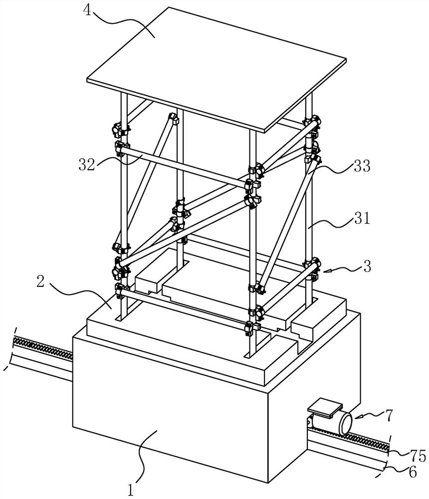
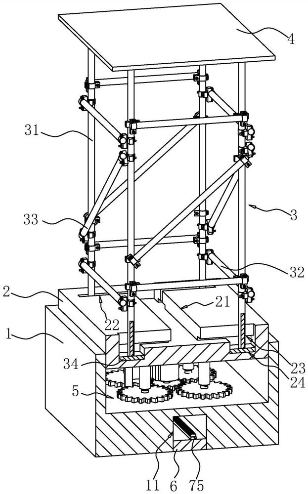
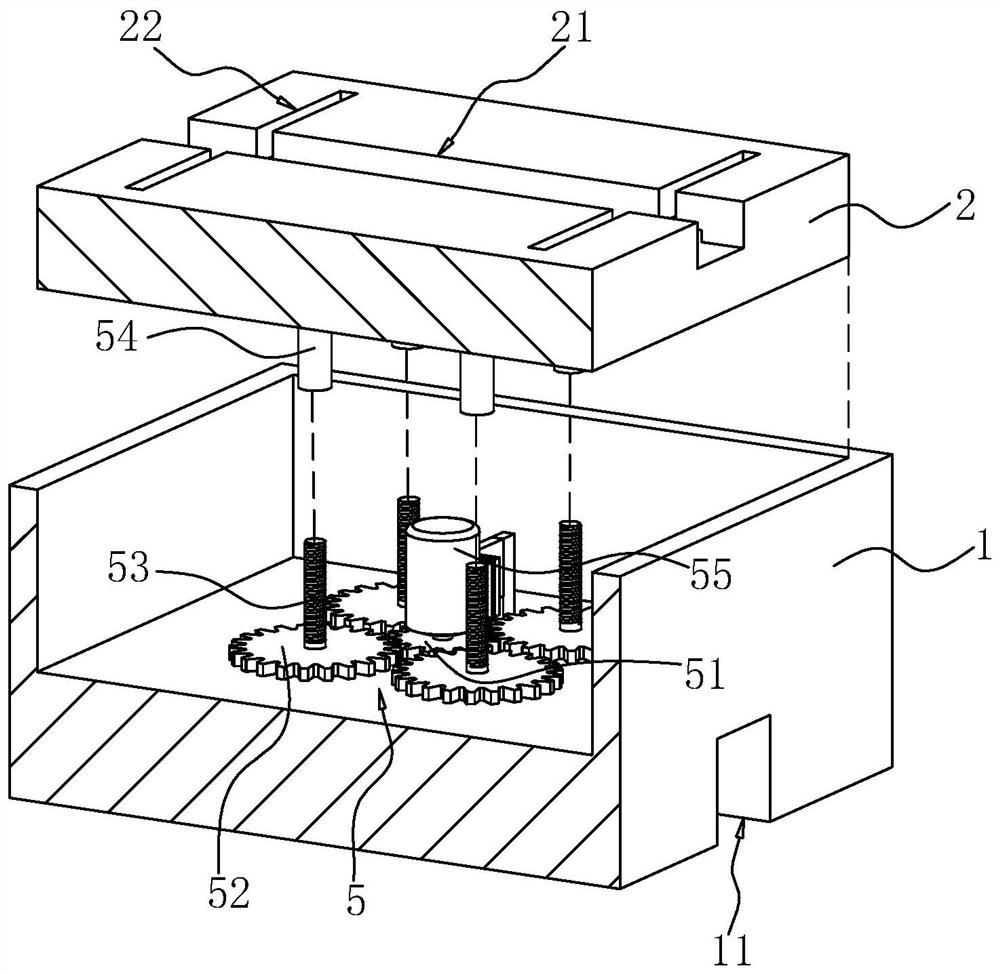
[0043] The embodiment of the present application discloses a cast-in-place bridge formwork support system device. refer to figure 1 and figure 2 , the template support system device includes several sliding boxes 1, a cavity is opened on the top surface of the sliding box 1, and a socket 2 is slidably inserted in the sliding box 1, and the formwork support system also includes several templates Bracket 3, a template bracket 3 is installed on each socket 2, and a template 4 is installed on the top of the template bracket 3; the inner bottom wall of the sliding box 1 is provided with a control socket 2 to raise or lower Complement component 5. Before the bridge construction, the operator lays a number of rails 6 according to the predetermined construction plan, and the rails 6 provide guidance for the movement of the sliding box 1 . The bottom surface of the sliding box 1 is prov...


PUM


Abstract

The invention relates to a cast-in-place bridge formwork support system device, and relates to the field of constructional engineering.The formwork support system comprises a plurality of formwork supports and a plurality of sliding box bodies, a bayonet socket is slidably inserted into each sliding box body, the formwork supports are installed on the bayonet sockets, formworks are installed on the formwork supports, a pouring mold is built on the formworks, and the formwork supports are connected with the sliding box bodies through bolts. A plurality of rails are laid on the ground of the bridge construction position, a mounting groove is formed in the bottom face of the sliding box body, the rail corresponding to the sliding box body is inserted into the mounting groove, a worm is rotationally connected into the mounting groove, a worm wheel meshed with the worm is rotationally connected into the mounting groove, and a sliding block is arranged in the worm wheel. A rotating shaft of the worm gear is fixedly connected with an intermediate gear, the upper surface of the track is fixedly connected with a rack, the intermediate gear is meshed with the rack, and the sliding box body is fixedly connected with a transmission motor for driving the worm to rotate. The construction method has the effect of improving the construction efficiency.

Description

technical field [0001] The application relates to the field of construction engineering, in particular to a cast-in-place bridge formwork support system device and a bridge cast-in-place rapid construction method. Background technique [0002] In the process of bridge construction, it is first necessary to formulate a construction plan, and then the operator builds a formwork support system according to the construction plan. The formwork support system includes several vertical bars, several horizontal bars, and several shear braces. The butt fasteners are connected between two adjacent vertical poles, and then the formwork is fixed on the vertical poles, and the pouring mold is built on the formwork. [0003] Sectional construction is widely used due to its small footprint, flexible construction and less impact on traffic. During the segmental construction of cast-in-situ bridges, concrete slurry is injected into the casting mold of the previous segment. When the concrete...

Claims


Application Information

Patent Timeline
Patent Type & Authority Applications(China)
IPC IPC(8): E01D21/00
CPCE01D21/00
Inventor 赵琪孟磊丁占胜姜新力王孝成康晓磊蒋龙
Owner SHANDONG LUQIAO CONSTR
Learn More