Dry roller multi-station rubber coating machine
A multi-station, glue-laminating machine technology, applied in the direction of household components, household appliances, other household appliances, etc., can solve problems such as rubber folds
- Summary
- Abstract
- Description
- Claims
- Application Information
AI Technical Summary
Problems solved by technology
Method used
Image
Examples
Embodiment 1
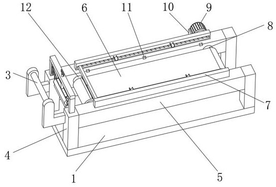
[0029] Embodiment one, by Figure 1-Figure 7 Provided, the present invention includes a base 1, the top sides of the base 1 are fixedly connected with a support base 4, and a connecting plate 5 is fixedly connected between the two supporting bases 4 located on the front and rear sides, and a connecting plate 5 is fixedly connected between the two connecting plates 5. A driven shaft 12 is movably connected, and a driving shaft 8 on the right side of the driven shaft 12 is movably connected between the two connecting plates 5. The rear end of the driving shaft 8 is fixedly connected to a motor 9, and a bracket is fixedly installed on the bottom of the motor 9. 10. The bracket 10 is fixedly connected to the connecting plate 5 on the rear side. The top of the connecting plate 5 is equidistantly provided with knife grooves 11. The top of the connecting plate 5 is equipped with a second rubber tensioning mechanism 7, and a rubber is installed above the conveyor belt 6. In the cuttin...
Embodiment 2
[0030]Embodiment 2, on the basis of Embodiment 1, the rubber cutting mechanism 2 includes U-shaped bars 201 fixedly connected to the connecting plate 5, the number of U-shaped bars 201 is three, and the three U-shaped bars 201 are equidistantly distributed On the top of the connecting plate 5, the top of the U-shaped bar 201 is movably connected with a riser 205, the top of the riser 205 is fixedly connected with a wedge-shaped block 206 at the top of the U-shaped bar 201, and the bottom of the riser 205 is fixedly connected with a mounting plate 204 , the bottom of the mounting plate 204 is fixedly connected with a cutting knife 203, and both sides of the top of the mounting plate 204 are fixedly connected with a sleeve 2010, the inner movable socket of the sleeve 2010 is connected with a first spring 2013, and the top of the first spring 2013 is connected with the The top of the U-shaped bar 201 is fixedly connected, the U-shaped bar 201 and the sleeve 2010 are fixedly connec...
Embodiment 3
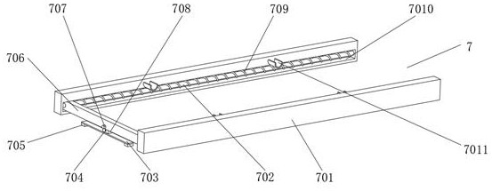
[0032] Embodiment 3, on the basis of Embodiment 1, the second rubber tensioning mechanism 7 includes two side plates 701 respectively located at the top of the two connecting plates 5, and the sides of the two side plates 701 close to each other are provided with chute 7010, the inside of the two chute 7010 is fixedly connected with a crossbar 702, the outside of the two crossbars 702 is movably connected with a slide bar 706, and the right side of the slide bar 706 is fixedly connected with two third springs 709, and the two second The three springs 709 are respectively movably socketed with the two cross bars 702, and the sides of the two side plates 701 close to each other are fixedly connected with two supporting blocks 7011, and the inside of the slide bar 706 is movably connected with an extruding plate 708, and the extruding plate The left side of 708 is provided with two screw holes 704, and the left side of slide bar 706 is equipped with the bolt 707 that matches with ...
PUM
 Abstract
Description
Claims
Application Information
 - R&D
- Intellectual Property
- Life Sciences
- Materials
- Tech Scout
- Unparalleled Data Quality
- Higher Quality Content
- 60% Fewer Hallucinations
Browse by: Latest US Patents, China's latest patents, Technical Efficacy Thesaurus, Application Domain, Technology Topic, Popular Technical Reports.
© 2025 PatSnap. All rights reserved.Legal|Privacy policy|Modern Slavery Act Transparency Statement|Sitemap|About US| Contact US: help@patsnap.com


