Fastening installation device for automobile mechanical parts
A technology of mechanical parts and installation devices, applied in the field of parts installation tools, can solve the problems of difficult installation of parts, difficult access by manpower, time-consuming and laborious manual rotation, etc., to avoid the rotation of the shaft and facilitate the tightening of bolts.
- Summary
- Abstract
- Description
- Claims
- Application Information
AI Technical Summary
Problems solved by technology
Method used
Image
Examples
Example Embodiment
[0055] Example 1:
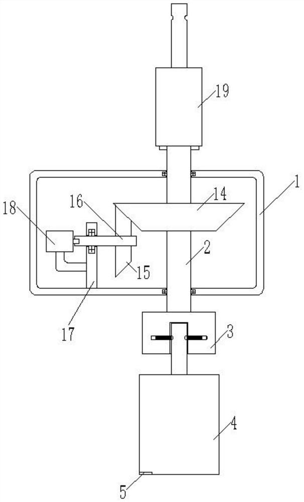
[0056] Such as figure 1As shown, the embodiment of the present invention provides an automobile mechanical component fastening device, including the outer casing 1; the first rotating shaft 2, longitudinal direction through the outer casing 1, and the upper and lower ends of the first spindle 2 are through the bearing Connect to the outer casing 1; the drive mechanism is fixed to the outer casing 1 for driving the first rotating shaft 2; the block 3 is fixed at one end of the first rotating shaft 2; the center of the block 3 is opened There is a longitudinal spline groove that matches the screw sleeve; the snap assembly is fixed within the block 3 for the tension screw sleeve 4; the control system, including: pressure sensor 5, fixed in the bottom of the screw sleeve The microprocessor 6 is connected to the driver of the pressure sensor 5 and the drive mechanism;
[0057] Here, when the microprocessor 6 receives the value of the pressure sensor 5, the microproc...
Example Embodiment
[0060] Example 2:
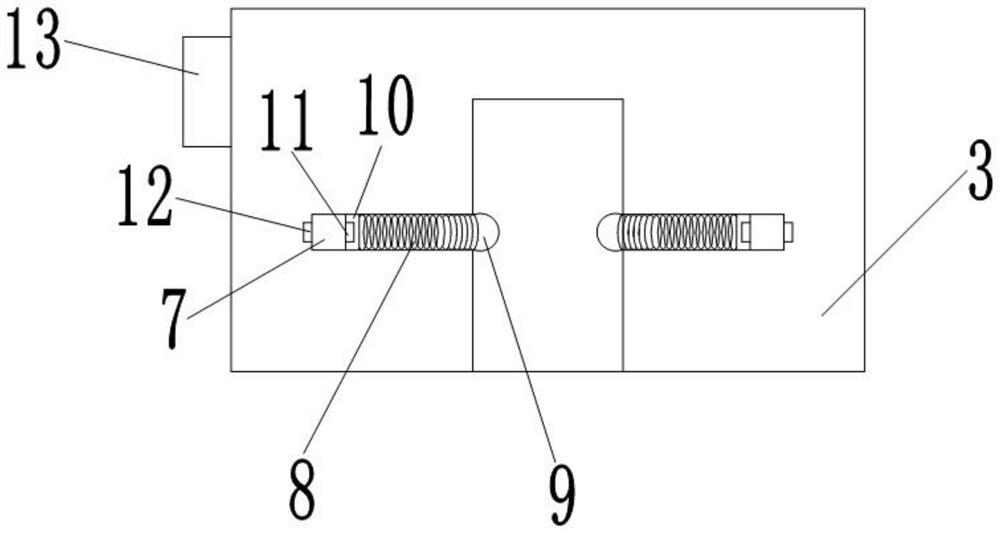
[0061] Based on Example 1, the block 3 is in the same horizontal surface having a plurality of grooves 7 in the circumferential homogeneous cloth, and each groove 7 is provided with a card connection assembly.
[0062] Further, the snap assembly includes a spring 8, placed within the recess 7; the spherical body 9 is fixed at one end of the spring 8; the first plate body 10, with the groove 7, and first On one side of the plate body 10 is fixed to one end of the spring 8 away from the spherical body 9; the first electromagnet 11 is fixed to the other side of the first plate 10; the first electromagnet 11 is connected to the microprocessor 6 The second electromagnet 12 is fixed to the recess 7 and the first electromagnet 11 is relatively placed; the second electromagnet 12 is connected to the microprocessor 6; the power source 13 is fixed in the block 3 The first electromagnet 11 and the connection line of the second electromagnet 12 are electrically connected t...
Example Embodiment
[0065] Example 3:
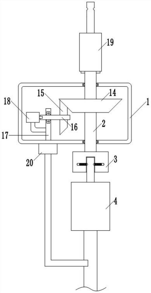
[0066] Based on Embodiment 1, the drive mechanism includes a driven beater gear 14, is fixed to the side wall of the first rotating shaft 2; the active cone gear 15, meshed with the slave gear 14; second The rotating shaft 16, through the center of the active cone 15; support seat 17, fixed within the outer casing 1, the second rotating shaft 16 penetrates through the support seat 17 and is connected to the support seat 17; the first motor 18 , Fixed to the outer casing 1, the output shaft of the first motor 18 is connected to one end of the second axis 16; the first motor 18 is a drive member of the drive mechanism, the first motor 18 and the microprocessor 6 connect.
[0067] The drive mechanism of the present invention ensures the stability of the rotation by engaging the active cone gear 15 and the slave gear 14 to rotate.
PUM
 Abstract
Description
Claims
Application Information
 - R&D Engineer
- R&D Manager
- IP Professional
- Industry Leading Data Capabilities
- Powerful AI technology
- Patent DNA Extraction
Browse by: Latest US Patents, China's latest patents, Technical Efficacy Thesaurus, Application Domain, Technology Topic, Popular Technical Reports.
© 2024 PatSnap. All rights reserved.Legal|Privacy policy|Modern Slavery Act Transparency Statement|Sitemap|About US| Contact US: help@patsnap.com


