Clamping piece and clamp

A technology for clamping parts and workpieces, which is applied in the direction of workpiece clamping devices, manufacturing tools, and devices for coating liquid on the surface, etc. It can solve the problem that the taper angle workpiece cannot be clamped and positioned, it is difficult to complete, and the size space and processing accuracy are strict. And other issues

Pending Publication Date: 2022-03-01
GUOGUANG ELECTRIC
View PDF0 Cites 1 Cited by
  • Summary
  • Abstract
  • Description
  • Claims
  • Application Information

AI Technical Summary

Problems solved by technology

[0002]With the development of market demand, the structure of the workpiece tends to become more and more complex shapes, such as irregular curved surfaces, planes, taper angles, etc. At this time, the traditional The positioning fixture can no longer meet the positioning requirements of the workpiece
In addition, as the workpiece becomes thinner and more refined, the dimensional space and machining accuracy reserved for the operator's positioning are becoming more and more stringent.
[0003]In the prior art, it is difficult to complete the workpiece positioning for the taper angle, and the structure is complicated
[0004] In order to solve the above problems, it is urgent to provide a clamping piece and fixture to solve the problem that the taper angle workpiece cannot be clamped and positioned

Method used


Image

  • Clamping piece and clamp
  • Clamping piece and clamp
  • Clamping piece and clamp

Examples


Embodiment Construction

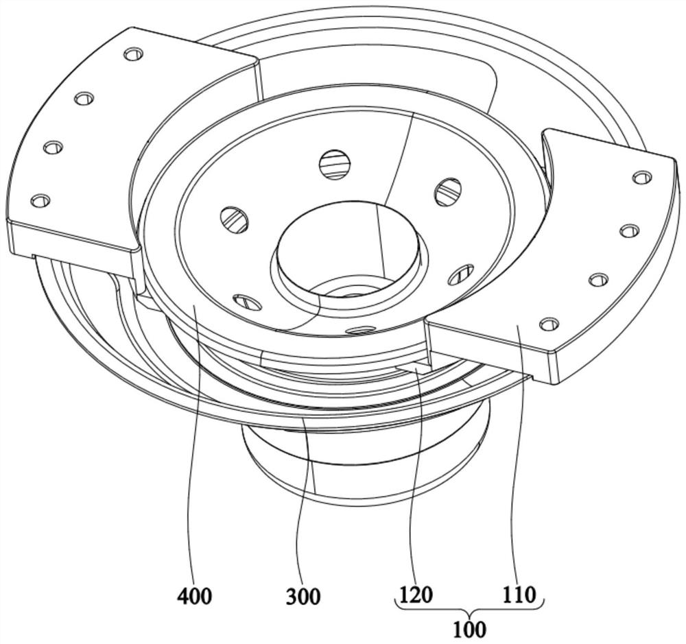
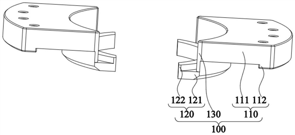
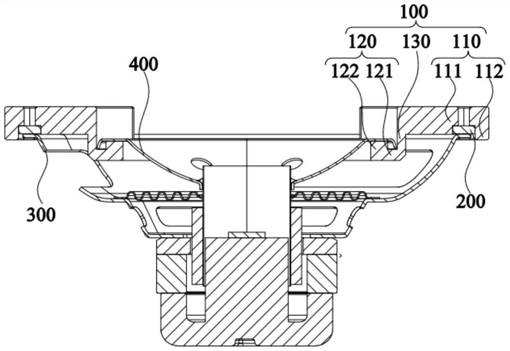
[0036] The present invention is further detailed below with reference to the accompanying drawings and examples. It will be appreciated that the specific embodiments described herein are merely illustrative of the invention and are not limited thereto. It will also be also to be explained, and only the structural points associated with the present invention are shown in the drawings.

[0037] In the description of the present invention, the term "connected", "connection", "fixed", unless otherwise specified, "connected", "fixed", for example, may be a fixed connection, or a detachable connection, or integral However, it can be a mechanical connection, or an electrical connection; it can be directly connected, or the intermediate medium can be indirectly connected, which may be a communication between the two elements or the interaction relationship of the two components. The specific meaning of the above terms in the present invention will be appreciated to those skilled in the ar...


PUM


Abstract

The invention relates to the technical field of part clamping and fixing, in particular to a clamping piece and a clamp. The clamping piece is used for positioning the relative position of the first workpiece and the second workpiece. The clamping piece comprises a main body, the main body comprises a first limiting part and a second limiting part, the first limiting part comprises a first end wall and a first limiting protrusion, the first limiting protrusion is connected with the first end wall and extends downwards, the inner wall of the first limiting protrusion can abut against the periphery of the first workpiece, and the edge of the second workpiece can be erected on the second limiting part. The limiting piece can restrain the second workpiece to move in the radial direction so as to connect the first workpiece and the second workpiece and fix the relative positions of the first workpiece and the second workpiece so that the second workpiece can be fixed through gluing. The structure is simple and convenient to operate, and the structures of the first limiting part and the second limiting part are beneficial to improving the limiting precision. According to the clamp, the second workpiece is clamped and fixed through the multiple clamping pieces, and operation is convenient and fast.

Description

Technical field [0001] The present invention relates to the field of partial clamping fixation techniques, and more particularly to a clamping member and a clamp. Background technique [0002] With the development of market demand, the structure of the workpiece tends to increasingly complex shapes, such as irregular surfaces, planes, taper angles, etc. At this time, the traditional positioning fixture can not meet the positioning requirements of the workpiece. In addition, as the workpiece is increasingly thin and high-transparent, the size space and processing accuracy of the reserved positioning to the operator are also harsh. [0003] In the prior art, the workpiece positioning for the taper angle is difficult to complete, and the structure is complex. [0004] In order to solve the above problems, it is urgent to provide a clamping member and a clamp to solve the problem that the taper angle workpiece cannot clamp the positioning. Inventive content [0005] It is an object ...

Claims


Application Information

Patent Timeline
IPC IPC(8): B25B11/00B05C13/00
CPCB25B11/00B05C13/00
Inventor 孔辉张垒张杰曹震凡赵轩
Owner GUOGUANG ELECTRIC
Why Eureka
Try Eureka