
Equipment illumination automatic adjusting method, device and system

An automatic adjustment and lighting driver technology, applied in the field of communication, can solve the problems of waste of resources, single way, fixed, etc., and achieve the effect of convenient resources and resource saving

Pending Publication Date: 2022-02-25
AEROSPACE INFORMATION
View PDF0 Cites 0 Cited by
  • Summary
  • Abstract
  • Description
  • Claims
  • Application Information

AI Technical Summary

Problems solved by technology

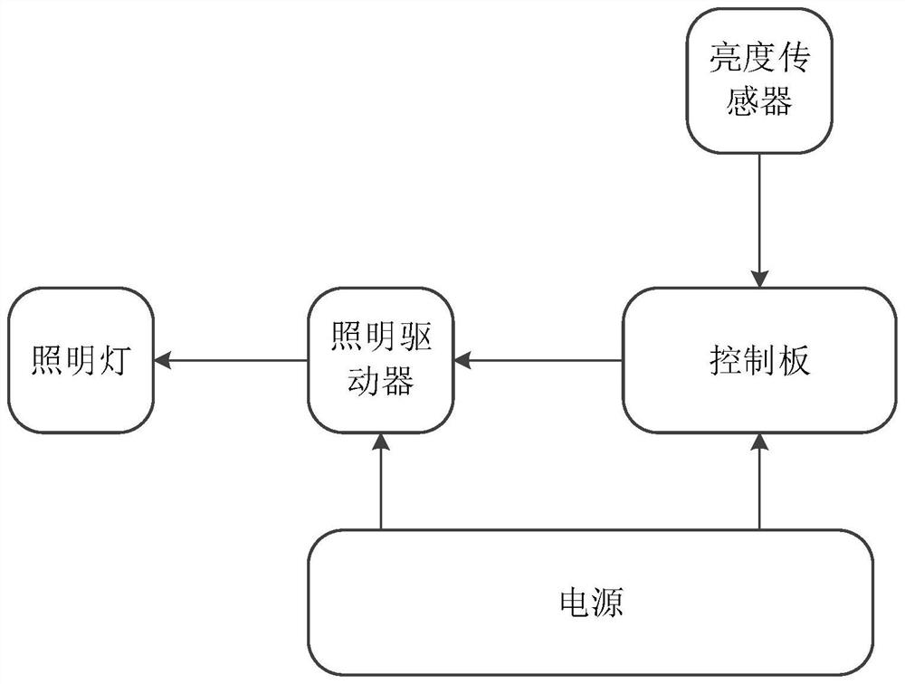
[0005] In view of this, the embodiments of the present invention provide a method, device and system for automatic adjustment of equipment lighting to solve the problem that the lighting system installed on the existing machine tool equipment is illuminated at the maximum brightness, and the method is single, fixed and wastes resources.

Method used


Image

  • Equipment illumination automatic adjusting method, device and system
  • Equipment illumination automatic adjusting method, device and system
  • Equipment illumination automatic adjusting method, device and system

Examples


Embodiment Construction

[0046] Embodiments of the present invention will be described in detail below in conjunction with the accompanying drawings.

[0047] It should be clear that the described embodiments are only some of the embodiments of the present invention, not all of them. Based on the embodiments of the present invention, all other embodiments obtained by persons of ordinary skill in the art without creative efforts fall within the protection scope of the present invention.

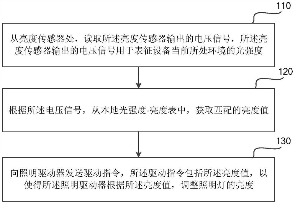
[0048] Attached below figure 1 , explain in detail the solutions provided by the embodiments of the present invention, figure 1 It is a flow chart of a method for automatically adjusting lighting of equipment provided by an embodiment of the present invention. In the embodiment of the present invention, the implementation subject is a control panel. Such as figure 1As shown, a method for automatically adjusting lighting of equipment provided by an embodiment of the present invention specifically includes the follow...


PUM


Abstract

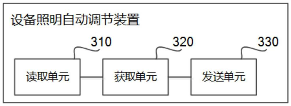
The embodiment of the invention discloses an equipment illumination automatic adjusting method, device and system, and relates to the technical field of communication. The method comprises the steps of reading a voltage signal output by a brightness sensor from the position of the brightness sensor, wherein the voltage signal output by the brightness sensor is used for representing the light intensity of the environment where equipment is located currently; acquiring a matched brightness value from a local light intensity-brightness table according to the voltage signal; and sending a driving instruction to a lighting driver, wherein the driving instruction comprises the brightness value so that the lighting driver adjusts the brightness of a lighting lamp according to the brightness value. The illumination brightness of the equipment is automatically adjusted by acquiring the light intensity of the surrounding environment of the equipment, and the method is flexible, convenient and resource-saving.

Description

technical field [0001] The present application relates to the field of communication technologies, and in particular to a method, device and system for automatically adjusting lighting of equipment. Background technique [0002] At present, on some large-scale machine tools (for example, numerically controlled machine tools), in order to facilitate managers to observe the operation of the machine tools, lighting systems are generally installed on the machine tools. This lighting system illuminates at maximum brightness. [0003] Due to the different environments of the machine tool equipment, some environments have relatively strong light, which does not require the machine tool equipment itself to be illuminated; while some ambient light is not very strong, which only requires proper lighting of the machine tool equipment itself. [0004] However, the lighting systems installed on the existing machine tools are all illuminated with maximum brightness, and the lighting syst...

Claims


Application Information

Patent Timeline
Patent Type & Authority Applications(China)
IPC IPC(8): H05B47/11
CPCH05B47/11Y02B20/40
Inventor 刘丙毓
Owner AEROSPACE INFORMATION
Learn More