
High-voltage switch cabinet

A high-voltage switchgear and cabinet technology, applied in the field of high-voltage switchgear, can solve the problems of not being able to meet the needs of workers to avoid rain, not being able to meet the protection of rainwater, and reducing the efficiency of cabinet sealing operations, so as to increase the dustproof effect, Increase the protection range and prevent the effect of impact

Inactive Publication Date: 2022-02-25
合肥巨步机械科技有限公司
View PDF1 Cites 0 Cited by
  • Summary
  • Abstract
  • Description
  • Claims
  • Application Information

AI Technical Summary

Problems solved by technology

[0005] The purpose of the present invention is to provide a high-voltage switchgear, through the design of the cabinet body, rainproof mechanism, drainage assembly, door body assembly, cabinet body sealing assembly and drainage assembly, it solves the problem that the existing high-voltage switchgear The top of the cabinet is protected from rain, which cannot meet the protection of rainwater in other directions, and cannot meet the needs of workers to avoid rain when it rains. When closing the cabinet door of the high-voltage switch cabinet, it is necessary to manually operate the sealing structure to realize the sealing of the cabinet body Dustproof, which greatly reduces the efficiency of the cabinet sealing operation. When there is no rainwater or the single rainwater cooling method is poor, the temperature in the cabinet cannot be dissipated in time, which makes the cooling effect of the cabinet poor.

Method used


Image

  • High-voltage switch cabinet
  • High-voltage switch cabinet
  • High-voltage switch cabinet

Examples


Embodiment 1

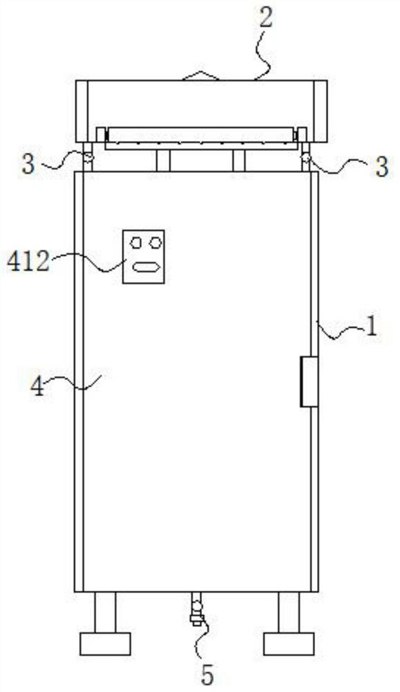
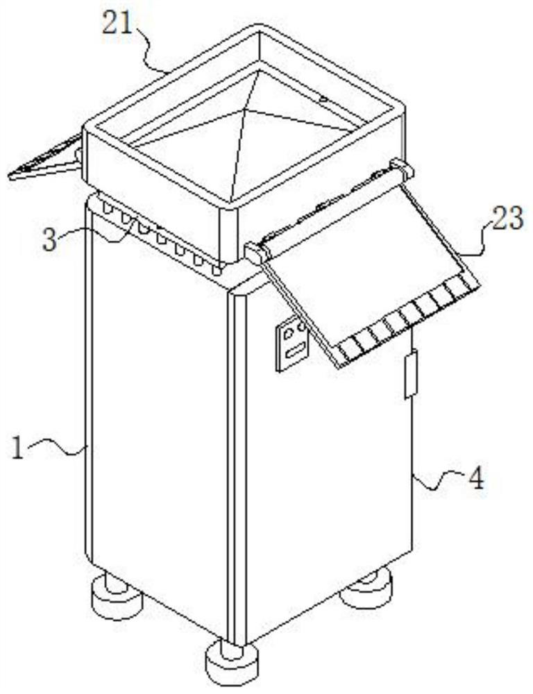
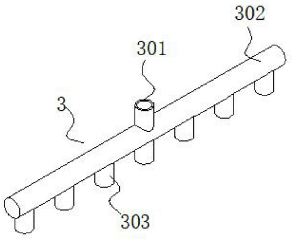
[0041] see Figure 1-6 and Figure 13 , the present invention is a high-voltage switchgear, including a cabinet body 1; a rain-proof mechanism 2 is fixed on the top of the cabinet body 1 for collecting rainwater, and at the same time, its structure can be expanded to expand the rain-proof range of the cabinet body 1, which can be used for For workers' shelter from the rain, two drainage components 3 are arranged between the rainproof mechanism 2 and the cabinet body 1. The drainage component 3 communicates with the inside of the rainproof mechanism 2, and the rainwater in the rainproof mechanism 2 can be guided through the setting of the drainage component 3. Flow out, used for the heat dissipation needs of the cabinet 1;

[0042] The cabinet wall of the cabinet body 1 is provided with several U-shaped cooling channels 101 in an array, and the two ends of the U-shaped cooling channels 101 run through the outer top of the cabinet body 1; the drainage assembly 3 communicates wi...

Embodiment 2

[0045] see Figure 1-15 , the present invention is a high-voltage switch cabinet. In this embodiment, the two vertical sections of the U-shaped heat dissipation channel 101 are arranged in the side wall of the cabinet body 1, and the horizontal section of the U-shaped heat dissipation channel 101 is arranged on the side wall of the cabinet body 1. In the bottom cabinet wall, by setting the heat dissipation structure of multiple cabinet walls in the cabinet body 1, the heat dissipation effect on the internal heat of the cabinet body 1 can be effectively increased;

[0046] The side of the cabinet body 1 away from the sealed door body structure 4 is fixedly equipped with an air induction device 102; the cabinet wall of the cabinet body 1 away from the sealed door body structure 4 is provided with a number of cooling air ducts 103 in an array, and one of the cooling air ducts 103 is connected with the induced draft air duct. The air duct of the equipment 102 is connected; the sid...

Embodiment 3

[0060] On the basis of Embodiment 2, the transverse seal 413 and the right-angle seal 421 are set as a structure filled with dust-absorbing materials. Under the action, the seal between the upper and lower gaps between the sealed door body 411 and the cabinet body 1 is realized. At the same time, the electromagnet 417 is energized by the controller 412. At this time, the electromagnet 417 has strong magnetism. The magnetic thrust between the magnet discs 426 pushes the two cabinet sealing components 42 to move along the guide slide bar 415 to the left and right sides of the cabinet 1, so that the right-angle seals 421 on the left and right sides are tightly attached to the sealed door body The sealing between 411 and the left and right sides of the cabinet body 1 greatly increases the sealing effect of the cabinet body 1 and effectively prevents dust from entering the interior of the cabinet body 1 and causing damage to electrical components.


PUM


Abstract

The invention discloses a high-voltage switch cabinet, and relates to the technical field of high-voltage switch cabinets. The high-voltage switch cabinet comprises a cabinet body, wherein a rainproof mechanism is fixed at the top part of the cabinet body, two drainage assemblies are arranged between the rainproof mechanism and the cabinet body, and the drainage assemblies are communicated with the interior of the rainproof mechanism; U-shaped heat dissipation channels are arranged in the cabinet wall of the cabinet body in an array mode, and the drainage assemblies are communicated with the U-shaped heat dissipation channels; and a sealing door body structure is hinged to the surface of the cabinet body, the sealing door body structure is composed of a door body assembly and two cabinet body sealing assemblies, the two cabinet body sealing assemblies are symmetrically arranged on the inner side, close to the cabinet body, of the door body assembly, and the cabinet body sealing assemblies are in sliding fit with the door body assembly. By arranging a water collecting assembly, a connecting assembly and a sheltering assembly, after the sheltering assembly is stretched and unfolded outwards, on one hand, rainwater protection in other directions can be met, the protection range of the high-voltage switch cabinet is enlarged, and on the other hand, the rain sheltering requirement of workers in rainy days can be met.

Description

technical field [0001] The invention belongs to the technical field of high-voltage switch cabinets, in particular to a high-voltage switch cabinet. Background technique [0002] Large-scale machinery and equipment are used in oil drilling and drilling. These equipment work requires a lot of electricity, so generally there are oil fields equipped with related power equipment. A very important piece of equipment in the power equipment is the high-voltage switchgear. There is a lot of dust in the process of oil and gas drilling, and the dust entering the high-voltage switchgear is easy to accumulate on electrical components, which may cause electrical components to short circuit or even cause a fire. At present, there have been high-voltage switch cabinets specially used for oil drilling and production, which can effectively prevent dust from entering the high-voltage switch cabinet during oil field drilling and production and affect its normal use. [0003] After retrieval, ...

Claims


Application Information

Patent Timeline
IPC IPC(8): H02B1/28H02B1/56H02B1/30
CPCH02B1/28H02B1/565H02B1/30
Inventor 牛犇
Owner 合肥巨步机械科技有限公司
Learn More