Supercharge Your Innovation With Domain-Expert AI Agents!

Clutch assembly with multifunctional lubricating oil circuit and gearbox

A technology for lubricating oil passages and clutches, which is applied to clutches, fluid-driven clutches, and non-mechanical-driven clutches. It can solve the problems of many oil passages, complex machining, and difficulty in processing lubricating oil passages, so as to reduce the difficulty and reduce the number of openings. Effect

Pending Publication Date: 2022-02-25
柳工柳州传动件有限公司 +1
View PDF0 Cites 0 Cited by
  • Summary
  • Abstract
  • Description
  • Claims
  • Application Information

AI Technical Summary

Problems solved by technology

The existing method needs to open more oil passages, and it is difficult to process lubricating oil passages on the box body, and the machining is complicated

Method used


Image

  • Clutch assembly with multifunctional lubricating oil circuit and gearbox
  • Clutch assembly with multifunctional lubricating oil circuit and gearbox
  • Clutch assembly with multifunctional lubricating oil circuit and gearbox

Examples


Embodiment 1

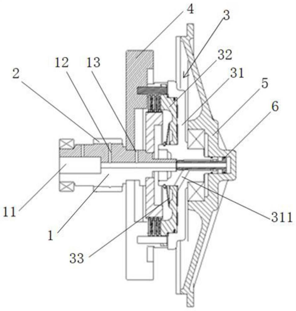
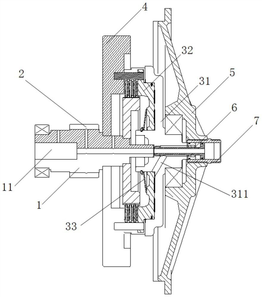
[0034] In the process of manufacturing gearboxes, in order to reduce the difficulty of opening oil passages, reduce the number of oil passages and reduce the difficulty of machining while ensuring lubrication and driving clutch action, such as Figure 1-Figure 2 As shown, the present invention provides a clutch assembly of a multifunctional lubricating oil circuit. The clutch assembly includes: rotating shaft 1, output gear 4, sun gear 2, clutch assembly 3 and lubricating shaft tube 6.

[0035] Wherein, along the axial direction of the rotating shaft 1, there is a lubricating oil channel 11 that runs through itself on the rotating shaft 1, and the lubricating oil channel 11 is coaxially arranged with the rotating shaft 1; the output gear 4 is rotatably arranged on the rotating shaft 1; The wheel 2 is fixed on the rotating shaft 1, specifically, in this embodiment, the sun gear 2 is integrated on the rotating shaft 1; the clutch assembly 3 is fixedly installed on the rotating s...

Embodiment 2

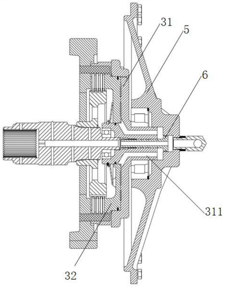
[0046] Such as image 3 As shown, the biggest difference between this embodiment and Embodiment 1 is that, in this embodiment, the lubricating shaft tube 6 can slide along the axial direction of the housing 31 , so as to adjust the pressure of the hydraulic oil pushing the piston 32 . Specific implementation manners are described below.

[0047] Because in the prior art, when putting into gear, the gear position oil channel of transmission valve is opened, and hydraulic oil enters the housing of clutch. When the oil passage valve of the transmission valve is opened, due to the "water hammer effect", the oil pressure increases suddenly, forming a pressure pulse, which pushes the piston 32 to move to the left, so that the steel plate and the friction plate are instantly combined, and there is no sliding friction process, and the gear is put on instantly. . Then, according to the principle of "water hammer effect", the pressure drops rapidly, and the steel plate and the frictio...


PUM


Abstract

The invention relates to the technical field of transmission devices, in particular to a clutch assembly with a multifunctional lubricating oil circuit and a gearbox. The clutch assembly comprises: a rotating shaft, wherein a lubricating oil way penetrating through the rotating shaft is formed in the rotating shaft in the axial direction of the rotating shaft, and the lubricating oil circuit and the rotating shaft are coaxially arranged; an output gear, wherein the output gear is rotationally arranged on the rotating shaft; a sun gear, wherein the sun gear is fixedly arranged on the rotating shaft; a clutch assembly, wherein the clutch assembly is arranged on the rotating shaft in a penetrating mode, and the output gear and the rotating shaft can be combined or separated through the clutch assembly; and a lubricating shaft tube,wherein the lubricating shaft tube is arranged on the clutch assembly in a penetrating manner and is communicated with the lubricating oil circuit. According to the invention, the difficulty of forming oil circuits can be reduced, the number of the formed oil circuits is reduced, the difficulty of machining is reduced, and meanwhile, the smoothness of gear shifting is ensured.

Description

technical field [0001] The invention relates to the technical field of transmission devices, in particular to a clutch assembly of a multifunctional lubricating oil circuit and a gearbox. Background technique [0002] The clutch assembly of the current gearbox is composed of a rotating shaft, a sun gear, a clutch and an output gear. The sun gear, clutch and output gear are arranged on the rotating shaft. The clutch is located between the sun gear and the output gear. The clutch assembly is located in the box In the hollow cavity formed by the body and the end cap. [0003] The sources of the shift hydraulic oil circuit and lubricating oil circuit of the clutch assembly are different. The hydraulic oil in the shift oil circuit enters the rotating shaft through the oil passage on the end cover to push the piston to move in the axial direction, so as to realize the adhesion between the friction plate and the steel plate of the clutch; the lubricating oil in the lubricating oil...

Claims


Application Information

Patent Timeline
IPC IPC(8): F16H57/04F16H57/023F16H57/031F16H57/02F16H61/00F16D25/12
CPCF16H57/043F16H57/0473F16H57/0423F16H57/0482F16H57/023F16H57/02F16H57/031F16D25/123F16H2061/0037F16H2061/0046
Inventor 莫艳芳徐强鄢万斌陈素姣蒋仁科陈礼光
Owner 柳工柳州传动件有限公司
Features
  • R&D
  • Intellectual Property
  • Life Sciences
  • Materials
  • Tech Scout
  • Unparalleled Data Quality
  • Higher Quality Content
  • 60% Fewer Hallucinations
Learn More