Tower foot anchoring structure for assembling tower and tower building method

An anchoring structure and tower foot technology, applied in construction, bridge construction, erection/assembly of bridges, etc., can solve the problems of affecting the construction progress, large amount of materials, harsh environmental requirements, etc., to increase the overall strength, the construction process is simple, shorten the The effect of the construction cycle

Active Publication Date: 2022-02-25
GUANGXI ROAD & BRIDGE ENG GRP CO LTD
View PDF8 Cites 0 Cited by
  • Summary
  • Abstract
  • Description
  • Claims
  • Application Information

AI Technical Summary

Problems solved by technology

[0003] However, the towers of the cable hoisting system for bridge construction are often more than 100 meters high, with large volume, large amount of materials, and complicated construction procedures, which require high anchoring effects for the foundation. For bridge construction in mountainous areas with steep slopes and deep ravines, work in mountain The surface is narrow and the environmental requirements are harsh. Generally, it is impossible to provide an effective working surface for the foundation. There is often no space for pouring a concrete layer with a certain thickness in a certain area, and it cannot provide an anchoring position for the tower. As a result, the tower installation requires a lot of manpower and material resources. and time, affecting the construction progress
[0004] Therefore, there is an urgent need for a technical solution to solve the technical problems of the existing cable hoisting system, which is difficult to fix the tower foot column, consumes a lot of manpower, material resources and time, and affects the construction progress.

Method used


Image

  • Tower foot anchoring structure for assembling tower and tower building method
  • Tower foot anchoring structure for assembling tower and tower building method
  • Tower foot anchoring structure for assembling tower and tower building method

Examples


Embodiment 1

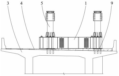
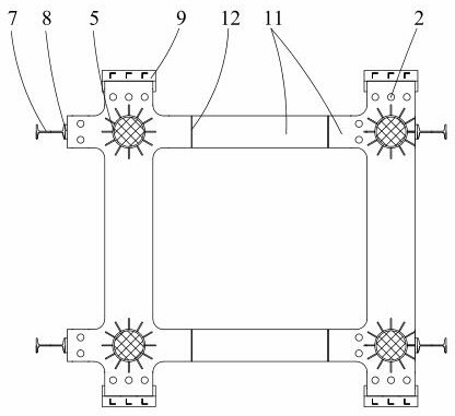
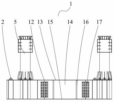
[0046] Such as Figure 1-Figure 13 As shown, a tower foot anchoring structure for an assembled tower in this embodiment is suitable for the tower foot anchoring of towers in the bridge construction process. The prestressed steel strand 2 is pre-embedded vertically in block 3 of 0#, and a pre-embedded pipe 41 is installed on block 3 of 0# corresponding to the column at the foot of the tower. The bottom of the pre-embedded pipe 41 is pre-embedded in block 3 of 0#. Extend 10-20cm, the beam body member 1 is placed on the top of the embedded pipe 41, anchored and fixed above the 0# block 3 through the prestressed steel strand 2, and the pipe body 5 is vertically arranged on the beam body member 1, and the pipe body 5 It is used to dock with the tower foot column.

[0047] In the tower foot anchorage structure for an assembled tower in this embodiment, prestressed steel strands 2 and pre-embedded pipes 41 are pre-embedded in the 0# block 3 reinforcement cage before the 0# block 3 i...

Embodiment 2

[0056] Such as Figure 1-Figure 13 As shown, a tower foot anchoring structure for an assembled tower in this embodiment has the same structure as that of Embodiment 1, the difference is that it also includes a number of limiting columns 7, which are pre-embedded in the top surface of 0# block 3 at least 30cm, protrude 0# block 3 at least 50cm, all limit columns 7 are arranged around beam body member 1, the distance between each limit column 7 and beam body member 1 is no more than 2cm, each limit column 7 and beam body The components 1 are abutted by setting embedded blocks 8 .

[0057] In the tower foot anchorage structure for an assembled tower in this embodiment, the limit column 7 is a vertically arranged I-beam, and the closed surface of the I-beam fits the side wall of the beam member 1, preventing the beam member 1 from The top surface of 0# block 3 has lateral slippage.

[0058] Specifically, before the 0# block 3 is poured, the limit column 7 is bound and fixed on t...

Embodiment 3

[0061] Such as Figure 1-Figure 13 As shown, a tower foot anchoring structure for an assembled tower in this embodiment has the same structure as Embodiment 1 or Embodiment 2, the difference is that it also includes a number of shear keys 9, and each shear key 9 includes arranging A number of L-shaped steels, the top of the shear key 9 is connected to the bottom of the beam member 1, the bottom is pre-embedded in the 0# block 3, and the shear key 9 is set at the position where the prestressed steel strand 2 passes through the top surface of the 0# block 3 outside.

[0062] In the tower foot anchorage structure for an assembled tower in this embodiment, the shear keys are six L-shaped steels arranged in double rows, connected as a whole by the top steel plate, and attached to the bottom surface of the beam member 1 by the top steel plate, and located at The prestressed steel strand 2 passes through the outside of the top surface of the 0# block 3 .

[0063] Specifically, befo...


PUM


Abstract

The invention relates to the field of cable hoisting system tower construction, in particular to a tower foot anchoring structure for assembling a tower and a tower building method. The tower foot anchoring structure comprises a beam body component and a plurality of prestressed steel strands, the prestressed steel strands are vertically pre-buried in 0 # blocks, a leveling layer is arranged on the top faces of the 0 # blocks, the beam body component is anchored to the top surface of the leveling layer through the prestressed steel strand, and the beam body component is used for anchoring a tower foot stand column. The tower is installed at the top of the 0 # block, the tower does not need to be installed in an independently arranged area on the ground, a stable foundation is provided for installation of the tower, the effect of fixing the tower is achieved, the tower can adapt to bridge construction in a mountainous area with a steep slope and a deep ravine, meanwhile, a permanent and temporary combined foundation is formed by the 0 # block, the prestressed steel strand and the beam body component, and after the tower is used, the tower can be detached easily, the overall strength of the 0 # block cannot be affected, the leveling layer can serve as a bridge deck structure, and manpower, material resources and time consumed in the tower building process are reduced.

Description

technical field [0001] The invention relates to the field of tower construction of a cable hoisting system, in particular to a tower foot anchoring structure for an assembled tower and a method for building the tower. Background technique [0002] The tower of the cable hoisting system is used for tensioning (supporting) hoisting cables to cooperate with the hoisting of components in bridge construction such as arch bridges, suspension bridges and cable-stayed bridges. The concrete layer of the tower is anchored by pre-embedded bolts to the tower foot column, and then assembled from bottom to top to realize the overall installation of the tower. [0003] However, the towers of the cable hoisting system for bridge construction are often more than 100 meters high, with large volume, large amount of materials, and complicated construction procedures, which require high anchoring effects for the foundation. For bridge construction in mountainous areas with steep slopes and deep ...

Claims


Application Information

Patent Timeline
Patent Type & Authority Applications(China)
IPC IPC(8): E01D21/00
CPCE01D21/00Y02E10/72Y02E10/728
Inventor 沈耀匡志强唐雁云罗小斌侯凯文叶增鑫黄志发黄崧孔垂昌黄酉马瑞艺
Owner GUANGXI ROAD & BRIDGE ENG GRP CO LTD
Why Eureka
Try Eureka