
Magnetic field generator calibration device and calibration method

A calibration device and calibration method technology, applied in the medical field, can solve the problems affecting the positioning accuracy of an electromagnetic navigation system, adverse effects on the treatment process, different positioning accuracy, etc., and achieve the effects of rapid calibration, high calibration accuracy, and simple calibration method.

Active Publication Date: 2022-02-22
成都思瑞定生命科技有限公司
View PDF8 Cites 2 Cited by
  • Summary
  • Abstract
  • Description
  • Claims
  • Application Information

AI Technical Summary

Problems solved by technology

[0004] The purpose of the present invention is to provide a magnetic field generator for the problem that the positioning accuracy of the existing magnetic field generators in the prior art is different at different positions in space, which seriously affects the positioning accuracy of the electromagnetic navigation system and adversely affects the treatment process. Instrument calibration device and calibration method

Method used


Image

  • Magnetic field generator calibration device and calibration method
  • Magnetic field generator calibration device and calibration method
  • Magnetic field generator calibration device and calibration method

Examples


Embodiment 1

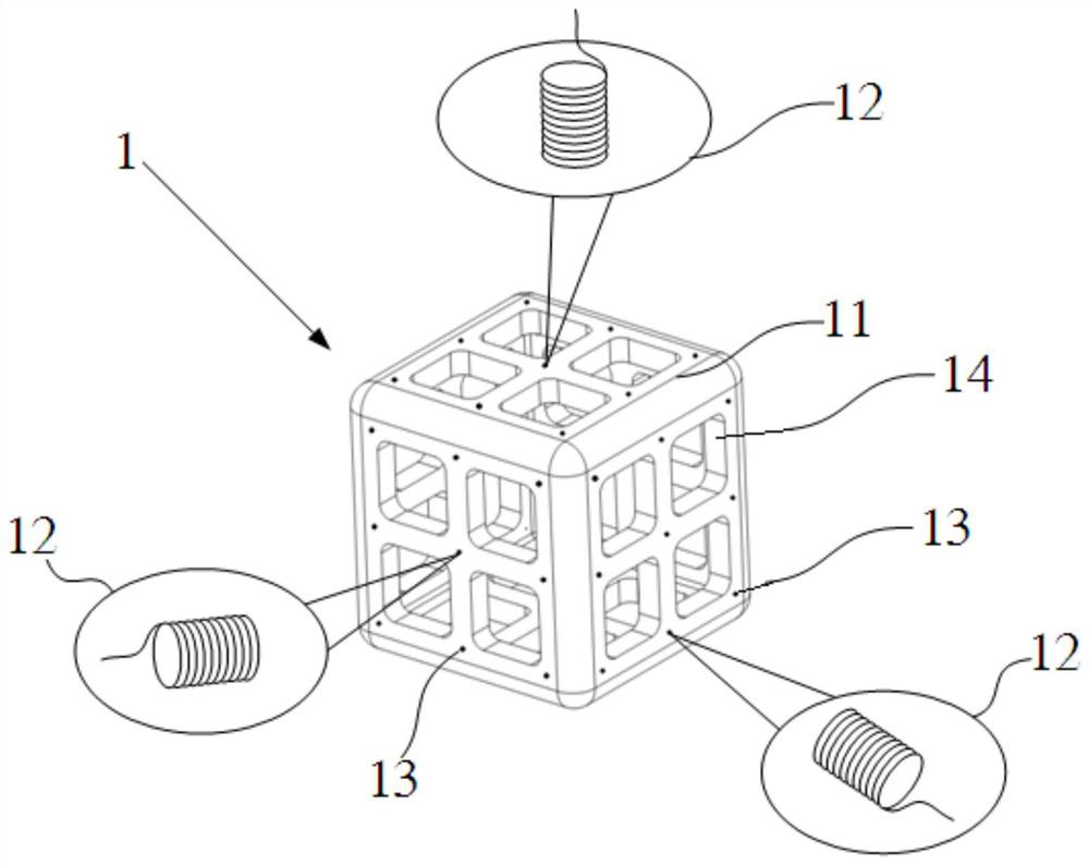
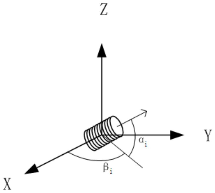
[0053] Such as figure 1As shown, a calibration device for a magnetic field generator includes an installation body 11, and in this embodiment, the installation body 11 is a regular hexahedron. The six surfaces of the mounting body 11 are provided with a plurality of insertion holes 13 , and in this embodiment, each surface is provided with 9 insertion holes 13 . The jacks 13 can be arranged horizontally, vertically or inclined at any angle. In this embodiment, the jacks 13 are all set perpendicular to the plane where they are located, so as to facilitate the calculation of the placement and placement of the jacks 13. Angle, the placement angle includes a pitch angle and an azimuth angle. A magnetic field sensor 12 is placed in the insertion hole 13 , and the shape and size of the insertion hole 13 are basically consistent with the magnetic field sensor 12 , so that the position of the magnetic field sensor 12 can be determined by the position of the insertion hole 13 . The m...

Embodiment 2

[0058] A method for calibrating a magnetic field generator, comprising the following steps:

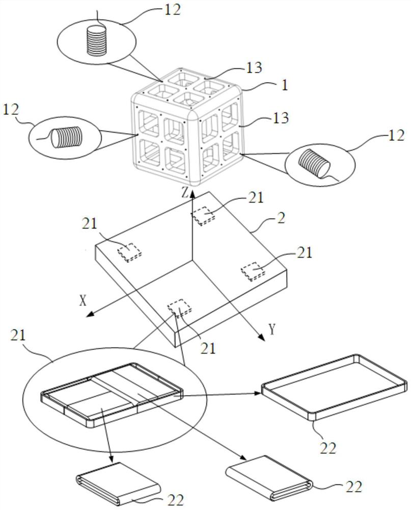
[0059] Step 1: If image 3 As shown, a magnetic field generator calibration device 1 as described in Embodiment 1 is placed on one side of the magnetic field generator 2 . In this embodiment, the calibration device 1 is placed above the magnetic field generator 2 . The magnetic field generator 2 includes four magnetic field generator groups 21, and each magnetic field generator group 21 includes three magnetic field generators 22, and the three magnetic field generators 22 are arranged in positions orthogonal to each other.

[0060] The distance between the magnetic field generator 22 and the magnetic field sensor 12 is greater than 10 times the size of the magnetic field generator 22 itself, that is, the distance between the magnetic field generator 22 and the tracking magnetic field sensor 12 is far greater than the size of the magnetic field generator 22 itself, Both can be consi...


PUM


Abstract

The invention discloses a magnetic field generator calibration device and calibration method, the calibration device comprises a mounting body, the mounting body is fixedly provided with at least six magnetic field sensors, the three-dimensional space positions and placement angles of the magnetic field sensors are known, and the placement angles comprise pitch angles and direction angles. The invention designs a magnetic field generator calibration device, the calibration device is a three-dimensional device provided with a plurality of magnetic field sensors with known relative positions, and the calibration device is used for determining the placement position and the placement direction of the magnetic field generator, so that the problem of different positioning precision of different spatial positions of the existing magnetic field generator can be solved; therefore, the magnetic field generator can be further optimized, and the use requirements of the medical field are better met. By adopting the calibration method provided by the invention, the magnetic field generator can be quickly calibrated, and the calibration method is simple and high in calibration precision.

Description

technical field [0001] The invention relates to the medical field, in particular to a calibration device and a calibration method for a magnetic field generator. Background technique [0002] The medical navigation and positioning system involves the tracking and positioning of objects (also known as detectors or magnetic field sensors) in three-dimensional space, and electromagnetic navigation is one of the widely used methods. Magnetic field generators and targets are involved in the electromagnetic navigation system. Common devices equipped with targets include catheters, guide wires, introducers (sheaths), probes, etc. The application fields include cardiac interventional therapy navigation, pulmonary bronchi positioning navigation, Renal artery ablation navigation, etc. [0003] The existing magnetic field generators have the disadvantage of different positioning accuracy at different positions in space, which seriously affects the positioning accuracy of the electroma...

Claims


Application Information

Patent Timeline
Patent Type & Authority Applications(China)
IPC IPC(8): A61B34/20
CPCA61B34/20A61B2034/2051
Inventor 陈传金
Owner 成都思瑞定生命科技有限公司
Learn More