Auxiliary winding device for power distribution maintenance

A wire winding and gear technology is applied in the field of auxiliary wire winding devices for power distribution maintenance, which can solve the problems of high labor and time consumption, inconvenient maintenance personnel, hidden safety hazards, etc., and achieves reasonable structure, good wire winding effect and wide application range. Effect

Pending Publication Date: 2022-02-18
ELECTRIC POWER OF HENAN LUOYANG POWER SUPPLY
View PDF10 Cites 0 Cited by
  • Summary
  • Abstract
  • Description
  • Claims
  • Application Information

AI Technical Summary

Problems solved by technology

[0002] In the process of power distribution maintenance, maintenance personnel often use cables of different sizes and lengths to cooperate with the maintenance. After the maintenance is completed, the cables often need to be wound for movement and storage. When the cables are long, manual methods are used. Winding wires not only consumes a lot of manpower and time, but also has certain potential safety hazards. Therefore, it is necessary to use mechanical devices to replace manual winding. Existing wire winding devices often use motors to horizontally or vertically Straight winding, after winding, due to the long wire, it is often difficult to remove the winding device and cable tightly, and the winding width of the winding device is fixed, and the winding width of the wire cannot be adjusted according to the size of the wire , which brings great inconvenience to the maintenance personnel; therefore, it is very necessary to provide an auxiliary winding device for power distribution maintenance with reasonable structure, good winding effect and wide application range

Method used


Image

  • Auxiliary winding device for power distribution maintenance
  • Auxiliary winding device for power distribution maintenance
  • Auxiliary winding device for power distribution maintenance

Examples


Embodiment 1

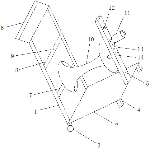
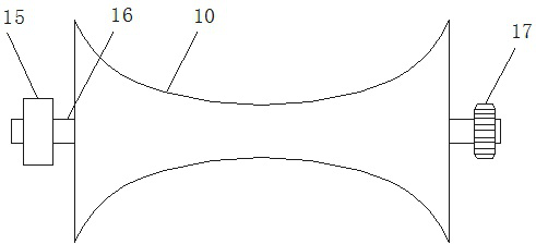
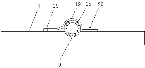
[0017] Such as Figure 1-4 As shown, an auxiliary winding device for power distribution maintenance, which includes a support frame body 1, a base 2 is provided at the bottom of the support frame body 1, and a walking wheel 3 and a support seat 4 are provided at the bottom of the base 2. The top of the support frame body 1 is provided with a cart handle 6, and the middle part of the support frame body 1 is provided with a first cross support frame 7 and a second cross support frame 8, and the first cross support frame 7 and the second cross support frame 8 The middle part is provided with an arc-shaped groove 9, and the other side of the base 2 is provided with a vertical support frame 5, and the vertical support frame 5 is provided with an upper through hole 12 and a lower through hole 14, and the upper through hole 12 and the lower through hole A motor 11 is fixedly arranged in the middle of the through hole 14, and the motor 11 is fixed on the vertical support frame 5 by a ...


PUM


Abstract

The invention relates to an auxiliary winding device for power distribution maintenance, which is characterized in that a base is arranged at the bottom of a supporting frame body, a first transverse supporting frame and a second transverse supporting frame are arranged in the middle of the supporting frame body, arc-shaped grooves are formed in the middle of the first transverse supporting frame and the middle of the second transverse supporting frame, a vertical supporting frame is arranged on the other side of the base, an upper through hole and a lower through hole are formed in the vertical supporting frame, a motor is fixedly arranged between the upper through hole and the lower through hole, the motor is fixed to the vertical supporting frame through a fixing frame, a winding device is arranged between an arc-shaped groove in the first transverse supporting frame and the first through hole, rotating rods are arranged at the two ends of the winding device, fixed bearings are arranged on the left sides of the rotating rods, the fixed bearings are placed in the arc-shaped grooves, a fixing clamp is further arranged on the outer side of the arc-shaped groove, the fixing clamp is rotationally arranged on the first transverse supporting frame through a rotating part, and the other end of the fixing clamp is arranged on the first transverse supporting frame through a limiting pin. The device has the advantages of being convenient to use, high in safety performance and easy to operate.

Description

technical field [0001] The invention relates to the technical field of electric power maintenance equipment, in particular to an auxiliary winding device for power distribution maintenance. Background technique [0002] In the process of power distribution maintenance, maintenance personnel often use cables of different sizes and lengths to cooperate with the maintenance. After the maintenance is completed, the cables often need to be wound for movement and storage. When the cables are long, manual methods are used. Winding wires not only consumes a lot of manpower and time, but also has certain potential safety hazards. Therefore, it is necessary to use mechanical devices to replace manual winding. Existing wire winding devices often use motors to horizontally or vertically Straight winding, after winding, due to the long wire, it is often difficult to remove the winding device and cable tightly, and the winding width of the winding device is fixed, and the winding width of...

Claims


Application Information

Patent Timeline
Patent Type & Authority Applications(China)
IPC IPC(8): B65H54/72B65H54/553B65H54/70
CPCB65H54/72B65H54/553B65H54/70B65H2701/34
Inventor 刘凯佘彦杰皇甫武军马晓飞黄磊峰刘燕东王朝乐李亮王松林
Owner ELECTRIC POWER OF HENAN LUOYANG POWER SUPPLY
Why Eureka
Try Eureka