High-rigidity numerical control machine tool cross beam assembly

A technology of CNC machine tools and assembly parts, which is applied in the field of CNC machine tools, can solve the problems of linear guide rail stiffness reduction, linear guide rail uneven force, and shortened service life, so as to increase machining accuracy, maintain force uniformity, and improve use. The effect of longevity

Inactive Publication Date: 2022-02-18
樟树市易正机械有限公司
View PDF0 Cites 0 Cited by
  • Summary
  • Abstract
  • Description
  • Claims
  • Application Information

AI Technical Summary

Problems solved by technology

The linear guide rail is installed on the guide rail mounting seat of the beam. The design of the guide rail mounting seat is various: two guide rail mounting seats are on the same vertical plane of the beam, one up and one down; or two guide rail mounting seats are respectively located on the vertical plane of the beam. There are two guide rail mounting seats on the surface and the horizontal plane, or on the front and rear vertical surfaces of the beam; then a linear guide rail is installed on the guide rail mounting seat, and the ram is connected with the linear guide rail through the slider on it to promote The two linear guides are subjected to tension in different directions, and the ram is equipped with a sliding column. Due to long-term cutting work, a certain angle is formed between the center line of the sliding column and the vertical direction, and the pressure on the lower linear guide increases. Under the influence of long-term alternating pressure and pressure, the force on the linear guide is uneven, so the stiffness of the linear guide is reduced, the service life is shortened, the stability is reduced, and the machining accuracy is affected.

Method used


Image

  • High-rigidity numerical control machine tool cross beam assembly
  • High-rigidity numerical control machine tool cross beam assembly
  • High-rigidity numerical control machine tool cross beam assembly

Examples


Embodiment Construction

[0028] In order to more clearly understand the above objects, features and advantages of the present invention, the present invention will be further described below in conjunction with the accompanying drawings and embodiments. It should be noted that, in the case of no conflict, the embodiments of the present application and the features in the embodiments can be combined with each other.

[0029] The present invention will be further described below in conjunction with the accompanying drawings and specific embodiments.

[0030] According to an embodiment of the present invention, such as Figure 1-9 displayed in:

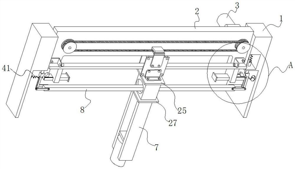
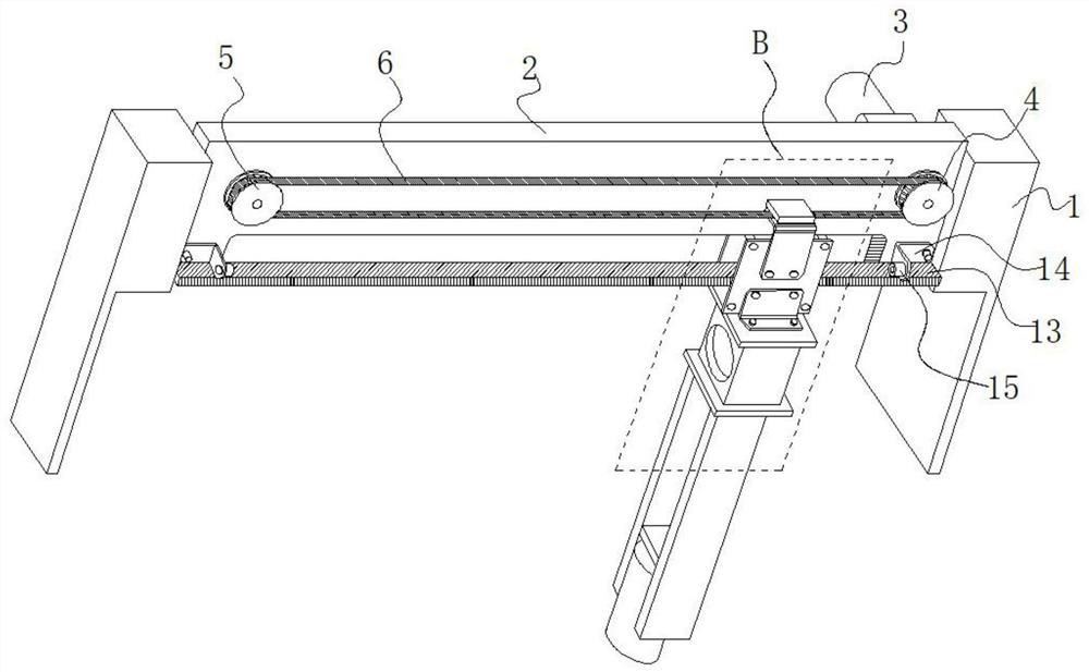
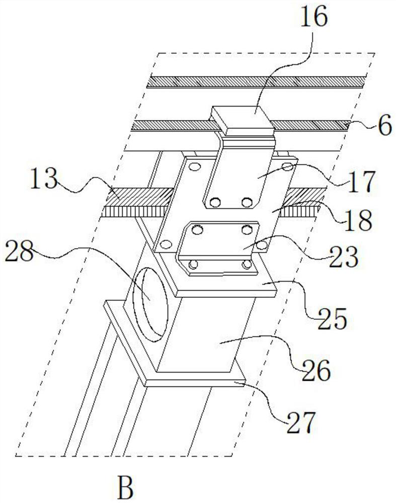
[0031] The present invention provides a numerically controlled machine tool crossbeam assembly with strong rigidity, which includes a symmetrically arranged column body 1, and a crossbeam 2 is arranged across the top of the corresponding side of the column body 1, and the crossbeam 2 is an inverted U-shaped structure. One end of the back side of the beam 2 is ...


PUM


Abstract

The invention discloses a high-rigidity numerical control machine tool cross beam assembly, which comprises symmetrically-arranged column bodies. A cross beam is transversely arranged between the tops of the corresponding side edges of the column bodies in a penetrating mode, the cross beam is of an inverted-U-shaped structure, a motor is arranged at one end of the back face of the cross beam, and the output end of the motor is connected with an output shaft; the output shaft penetrates through the cross beam and extends to the front side of the cross beam, a main chain wheel is arranged at the end of the output shaft, a secondary chain wheel is arranged at the other end of the front face of the cross beam and connected with the main chain wheel through a chain, a clamping mechanism is arranged on the chain, and a machining head is arranged on the clamping mechanism. Symmetrical balance mechanisms are arranged on the lower portions of the corresponding side edges of the column body, a balance guide plate is arranged between the balance mechanisms at the two ends, the balance guide plate is of a cavity structure, a plurality of balls are arranged in the balance guide plate, and the numerical control machine tool cross beam assembly has the advantages of being high in rigidity, long in service life, good in stability and even in stress.

Description

technical field [0001] The invention relates to the technical field of numerical control machine tools, in particular to a beam assembly of a numerical control machine tool with strong rigidity. Background technique [0002] At present, most of the beam structures of the existing CNC machine tools use linear guide rail devices. The linear guide rail is installed on the guide rail mounting seat of the beam. The design of the guide rail mounting seat is various: two guide rail mounting seats are on the same vertical plane of the beam, one up and one down; or two guide rail mounting seats are respectively located on the vertical plane of the beam. There are two guide rail mounting seats on the surface and the horizontal plane, or on the front and rear vertical surfaces of the beam; then a linear guide rail is installed on the guide rail mounting seat, and the ram is connected with the linear guide rail through the slider on it to promote The two linear guides are subjected to ...

Claims


Application Information

Patent Timeline
IPC IPC(8): B23Q1/01
CPCB23Q1/01
Inventor 张永强
Owner 樟树市易正机械有限公司
Why Eureka
Try Eureka