Camera light supplement control method and device
A control method and camera technology, applied in image communication, color TV parts, TV system parts, etc., can solve the problems of inability to perform local exposure, overexposure, and only one brightness, etc., to achieve local Exposure, improve fill light effect and photo effect, avoid overexposure effect
- Summary
- Abstract
- Description
- Claims
- Application Information
AI Technical Summary
Problems solved by technology
Method used
Image
Examples
Embodiment 1
[0030] According to an embodiment of the present invention, an embodiment of a method for controlling light supplement of a camera is provided. It should be noted that the steps shown in the flow chart of the accompanying drawings can be executed in a computer system such as a set of computer-executable instructions, Also, although a logical order is shown in the flowcharts, in some cases the steps shown or described may be performed in an order different from that shown or described herein.
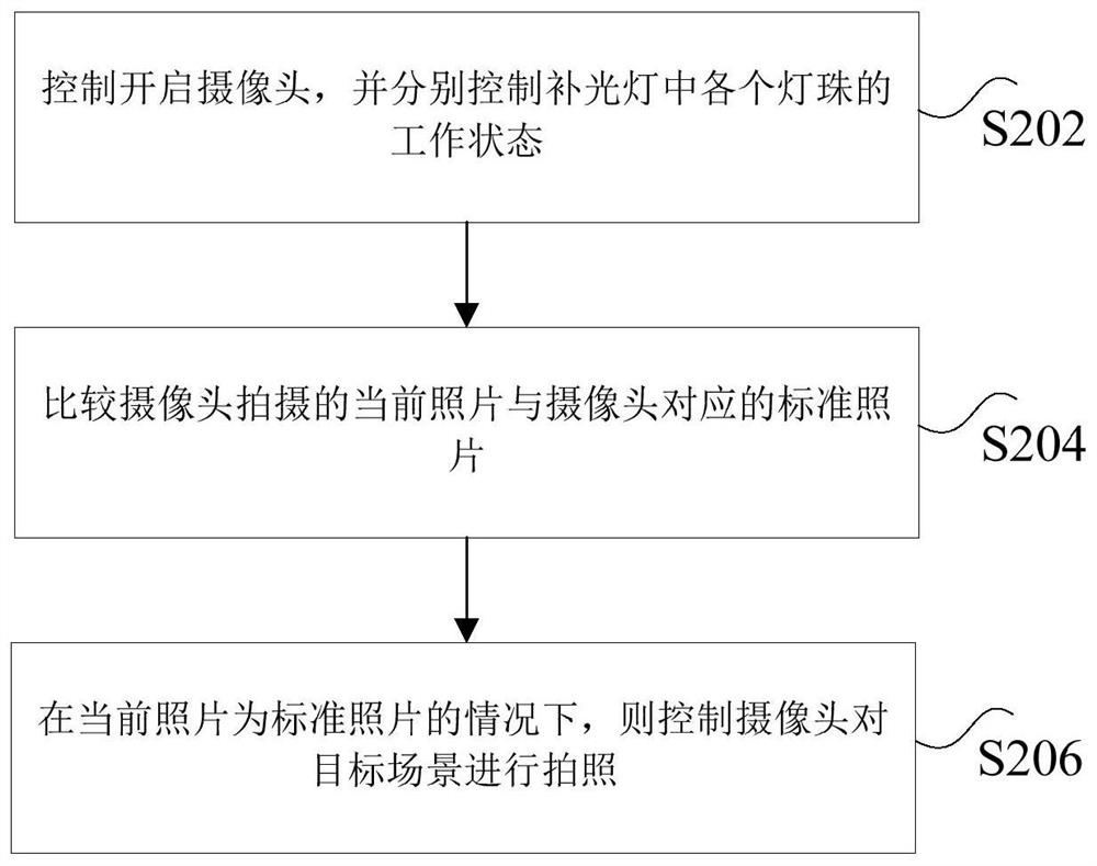
[0031] figure 2 It is a flowchart of a method for controlling light supplement of a camera according to an embodiment of the present invention, such as figure 2 As shown, the method for controlling the supplementary light of the camera includes the following steps:
[0032] Step S202, controlling to turn on the camera, and separately controlling the working status of each lamp bead in the fill light;
[0033] In an optional implementation, the control to turn on the camera can be don...
Embodiment 2
[0067] According to another aspect of the embodiments of the present invention, a control device for supplementary light of a camera is also provided, Image 6 is a schematic diagram of a control device for supplementary light of a camera according to an embodiment of the present invention, as shown in Image 6 As shown, the camera supplementary light control device includes: a first control module 62 , a comparison module 64 and a second control module 66 . The control device for supplementary light of the camera will be described in detail below.
[0068] The first control module 62 is used to control the opening of the camera, and respectively controls the working status of each lamp bead in the supplementary light; the comparison module 64 is connected to the above-mentioned first control module 62, and is used to compare the current photo taken by the camera with the corresponding camera The standard photo is used to obtain the comparison result; the second control modul...
Embodiment 3
[0078] According to another aspect of the embodiments of the present invention, there is also provided a computer-readable storage medium, the computer-readable storage medium includes a stored program, wherein, when the program is running, the device where the computer-readable storage medium is located is controlled to execute any of the above-mentioned A method for controlling the fill light of a camera.
[0079] Optionally, in this embodiment, the above-mentioned computer-readable storage medium may be located in any computer terminal in the computer terminal group in the computer network, and / or in any mobile terminal in the mobile terminal group, and the above-mentioned computer may The read storage medium includes stored programs.
[0080] Optionally, when the program is running, the device where the computer-readable storage medium is located is controlled to perform the following functions: control to turn on the camera, and respectively control the working status of ...
PUM
 Abstract
Description
Claims
Application Information
 - R&D Engineer
- R&D Manager
- IP Professional
- Industry Leading Data Capabilities
- Powerful AI technology
- Patent DNA Extraction
Browse by: Latest US Patents, China's latest patents, Technical Efficacy Thesaurus, Application Domain, Technology Topic, Popular Technical Reports.
© 2024 PatSnap. All rights reserved.Legal|Privacy policy|Modern Slavery Act Transparency Statement|Sitemap|About US| Contact US: help@patsnap.com


