
Built-in permanent magnet variable frequency transformer based on magnetic field modulation principle and design method

A magnetic field modulation and built-in technology, which is applied in AC/AC converters, electromechanical devices, manufacturing motor generators, etc., can solve the problems that the efficiency is difficult to further improve, and achieve superior performance, taking into account its own characteristics, and filtering harmonics Effect

Active Publication Date: 2022-02-15
XI AN JIAOTONG UNIV
View PDF9 Cites 0 Cited by
  • Summary
  • Abstract
  • Description
  • Claims
  • Application Information

AI Technical Summary

Problems solved by technology

However, this device requires an external DC motor to drive the rotor, and the efficiency is difficult to further improve
[0004] High-power electromagnetic power conversion devices have a broad application space in our country, but there are few domestic researches on this aspect at present, and there is no economical method in the field of power frequency conversion. Devices with high reliability, high operational reliability and superior performance are applied, and this technology should be further studied and promoted in a timely manner.

Method used


Image

  • Built-in permanent magnet variable frequency transformer based on magnetic field modulation principle and design method
  • Built-in permanent magnet variable frequency transformer based on magnetic field modulation principle and design method
  • Built-in permanent magnet variable frequency transformer based on magnetic field modulation principle and design method

Examples


Embodiment 1

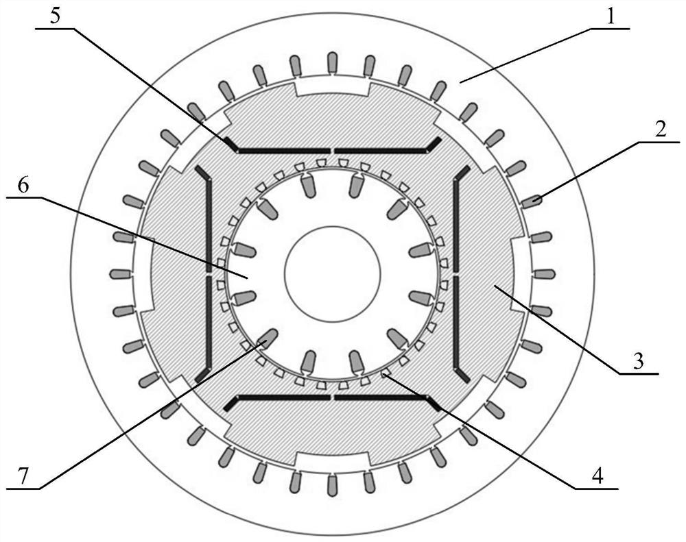
[0049] refer to figure 2 , this embodiment takes triple frequency conversion as an example, the built-in permanent magnet variable voltage converter based on the magnetic field modulation principle includes an outer stator core 1, an outer stator winding 2, a rotary magnetic ring, an inner stator core 6 and Inner stator winding 7;

[0050] Among them, the inner stator core 6, the rotary magnetic adjustment ring and the outer stator core 1 are distributed sequentially from the inside to the outside, and the inner stator winding 7 is wound on the inner stator core 6, and the outer stator winding 2 is wound on the outer stator core 1 Inside, the outer wall of the rotary magnetic adjustment ring is provided with a salient pole magnetic adjustment block 3, the inner permanent magnet 5 is arranged in the rotary magnetic adjustment ring, and the starting cage 4 is arranged on the inner wall of the rotary magnetic adjustment ring;

[0051] In this embodiment, the inner stator windin...


PUM


Abstract

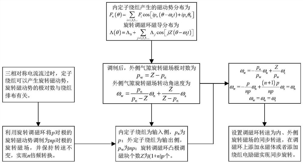
The invention discloses a built-in permanent magnet variable frequency transformer based on a magnetic field modulation principle and a design method. The method comprises the following steps: additionally arranging a rotary magnetic field adjusting ring between an inner stator iron core and an outer stator iron core, arranging a built-in permanent magnet in the rotary magnetic field adjusting ring, and arranging a salient pole magnetic field adjusting block on the outer wall of the rotary magnetic field adjusting ring; modulating the rotating magnetomotive force generated by the inner stator windings of p pole pair into a rotating magnetic field of np pole pair by using the rotary magnetic field adjusting ring, enabling the rotating magnetic field to correspond to the np pole pair of an outer stator winding, and enabling the rotating magnetomotive force generated by the inner stator winding and the modulated three-phase rotating magnetic field to rotate at a synchronous rotating speed; and making the modulated rotating magnetic field to induce n-frequency-doubled symmetrical three-phase alternating-current voltage in the outer stator winding. According to the invention, by means of the built-in permanent magnet variable frequency transformer and the design method, electric energy frequency conversion can be achieved, and the built-in permanent magnet variable frequency transformer has the advantages of being high in economical efficiency, high in operation reliability and excellent in performance.

Description

technical field [0001] The invention belongs to the technical field of new energy and electric power engineering, and in particular relates to a built-in permanent magnet variable voltage converter and a design method based on the magnetic field modulation principle. Background technique [0002] The power grid is an important infrastructure related to the national economy, a carrier of power transmission and an important platform for the optimal allocation of energy resources. In recent years, especially with the accelerated development of clean energy and the popularization and application of grid intelligent technology, the traditional power system is rapidly showing new characteristics of high proportion of power electronics and high proportion of new energy power supply. Due to the reverse distribution of energy and productivity in our country, and energy production is far away from the power load center, in order to meet the growing demand for electricity in economic a...

Claims


Application Information

Patent Timeline
Patent Type & Authority Applications(China)
IPC IPC(8): H02K47/18H02K47/22H02K16/04H02K15/00
CPCH02K47/18H02K47/22H02K16/04H02K15/00H02K2213/03Y02E10/76
Inventor 王曙鸿骆力州寇可焓段娜娜张那明张军王锡凡王秀丽张寅捷
Owner XI AN JIAOTONG UNIV
Learn More