Reservoir porous medium flow temperature coupling model calculation method based on windward GFDM
A technology of porous media and coupled models, applied in the field of mass transfer and heat transfer coupling, can solve problems such as high-quality grids with limited geometric regularity
- Summary
- Abstract
- Description
- Claims
- Application Information
AI Technical Summary
Problems solved by technology
Method used
Image

Examples
Embodiment 1
[0076] An embodiment of the present invention provides a method for calculating a fluid-temperature coupling model of a porous medium in a reservoir based on upwind GFDM, including the following steps:
[0077] S1. Establish a porous medium flow-temperature coupling model of the reservoir;
[0078] The porous medium flow-temperature coupling model includes a substance conservation equation, an energy conservation equation and an auxiliary equation:
[0079] Wherein, assuming that the fluid is incompressible, the conservation equation of matter is:
[0080]
[0081] In the above formula: k is permeability, mD; t is time, day; μ(T) is fluid viscosity related to temperature, mPa s; p is pressure, MPa; q is source-sink term, 1 / day; (p,T) is the reservoir porosity related to pressure and temperature;
[0082] The energy conservation equation is:
[0083]
[0084] In the above formula: T is temperature, ℃; λ c (p,T) is the comprehensive heat transfer coefficient related to...
Embodiment 2
[0166] Validation of upstream rights format
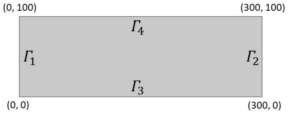
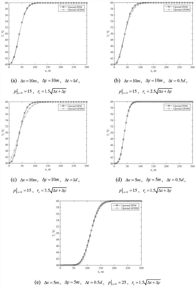
[0167] In this embodiment, a regular rectangular calculation domain ([0m, 300m]×[0m, 100m]) is selected, and the values of relevant physical parameters are shown in Table 1. In this embodiment, the upstream weight format only involves the heat convection item, Therefore, in this embodiment, the compression coefficient, thermal expansion coefficient, and viscosity-temperature coefficient are set to 0, and the upper and lower boundaries are closed boundary conditions, and the left and right boundaries are constant pressure and constant temperature boundary conditions. For the specific equations, see equation (25 and equation (26) to construct A stable seepage field independent of temperature distribution can be obtained to better control other variables and only analyze the validity of the upstream weight format of formula (10).
[0168] Table 1 Physical parameter values
[0169] Permeability k 500mD Fluid heat tra...
Embodiment 3
[0184] Homogeneous Reservoir Study
[0185] Such as Figure 4 As shown, this embodiment is an irregular polygonal computational domain. Equation (30) and Equation (31) respectively show the boundary conditions and initial value conditions for pressure and temperature. It can be seen that the left boundary and right The boundary is the first type of boundary condition, and the upper and lower boundaries are closed boundary conditions. The values of relevant physical parameters are shown in Table 2. It can be seen that the permeability in the calculation domain of this embodiment is a constant, representing a homogeneous porous medium reservoir.
[0186]
[0187]
[0188] Table 2 Physical parameter values
[0189]
[0190] Figure 5 Shows the fine triangular mesh, rough triangular mesh and collocation points used in the GFDM calculation of this embodiment. The collocation points are derived from the nodes in the rough triangular mesh. It should be pointed out that t...
PUM
 Abstract
Description
Claims
Application Information
 - R&D
- Intellectual Property
- Life Sciences
- Materials
- Tech Scout
- Unparalleled Data Quality
- Higher Quality Content
- 60% Fewer Hallucinations
Browse by: Latest US Patents, China's latest patents, Technical Efficacy Thesaurus, Application Domain, Technology Topic, Popular Technical Reports.
© 2025 PatSnap. All rights reserved.Legal|Privacy policy|Modern Slavery Act Transparency Statement|Sitemap|About US| Contact US: help@patsnap.com