
Displacement device

A displacement device and guide rail technology, which is applied in the direction of large fixed members, metal processing machinery parts, maintenance and safety accessories, etc., can solve the problems of limiting the scope of application of displacement devices and limiting the scope of application of technical solutions, so as to improve the scope of application and reduce manufacturing cost. Effects of Difficulty and Cost

Active Publication Date: 2022-02-15
YINGUAN SEMICON TECH CO LTD
View PDF8 Cites 0 Cited by
  • Summary
  • Abstract
  • Description
  • Claims
  • Application Information

AI Technical Summary

Problems solved by technology

[0003] At present, the existing displacement device has a balance mass design that considers the planar movement under the air bearing support. Although it can meet the role of counter force guidance, because the air bearing support is used, this technical method is limited to the atmospheric environment. It is only effective when used, which limits the scope of application of the displacement device
[0004] Of course, there is also a balance mass design used in a vacuum environment, but the corresponding technology is limited to the balance mass design of a single motion axis, which is mainly used as a reaction force guiding mechanism for the main motion axis, and has no effect on the motion reaction force and displacement of other motion axes. Play the role of counter force guidance, which also limits the scope of application of its technical solutions

Method used


Image

  • Displacement device
  • Displacement device
  • Displacement device

Examples


Embodiment 5

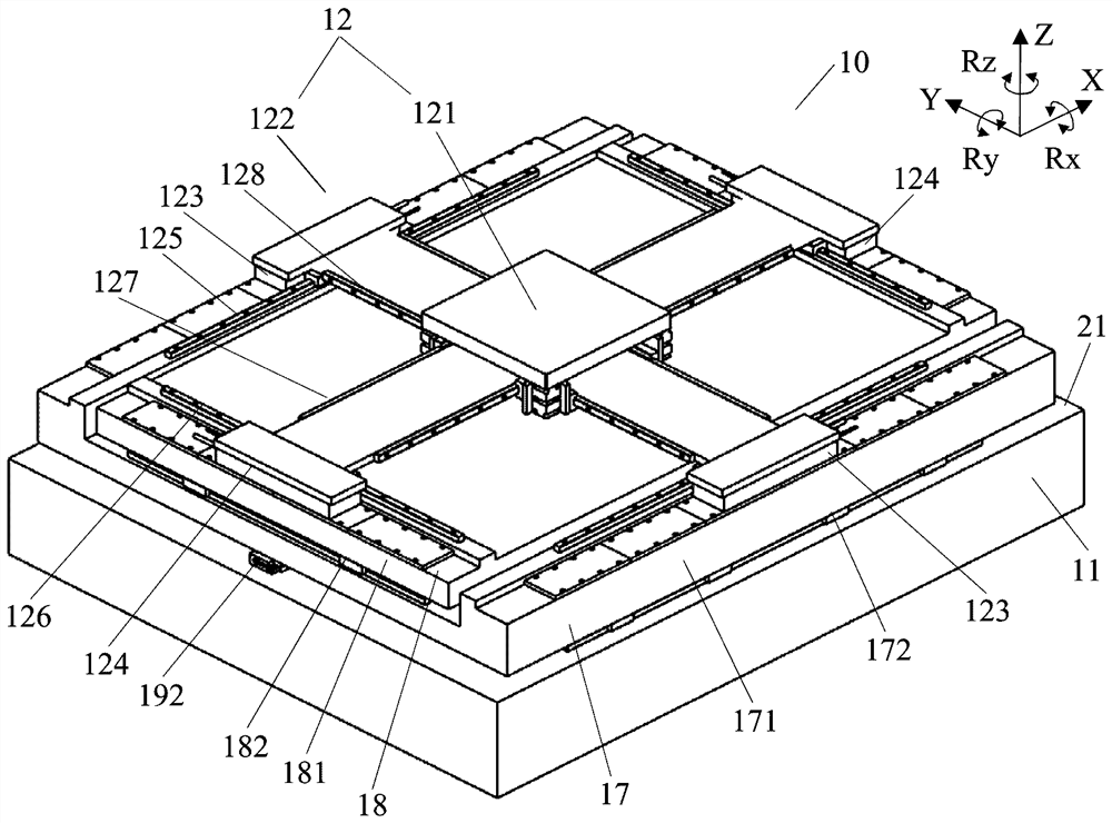
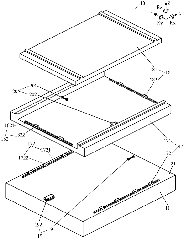
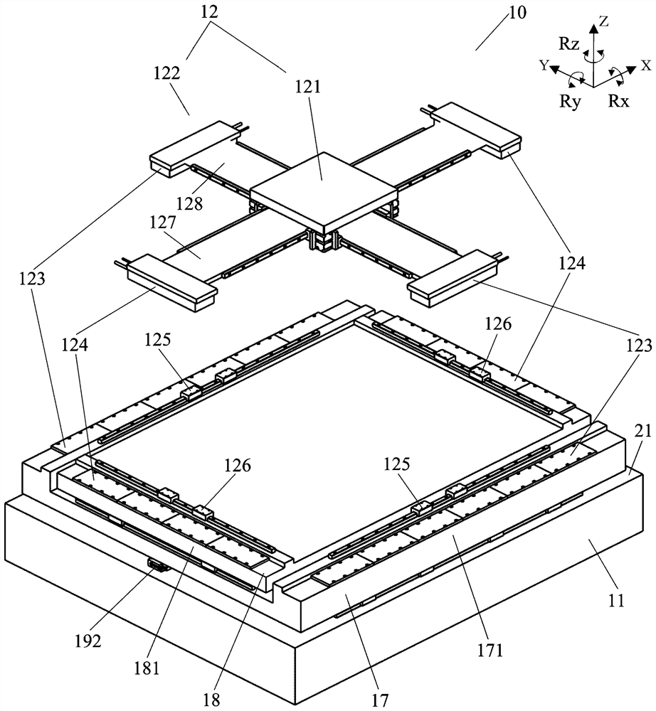
[0112] Compared with embodiment 5 and embodiment 6, embodiment 5 does not need to set the cable table assembly for the moving platform 12 to drag the pipes and cables, but can solve the problem of power supply by arranging the pipes and cables inside the second mass part 181 and air supply, this simplifies the structural space layout of the displacement device 10 to a certain extent, and can make the structural design more compact.

[0113] In addition, in another embodiment not shown in the figure, one side of the first cable platform 13 and the second cable platform 14 in the double cable platform assembly can also be respectively connected to the second side of the second balance mass part 18. On the mass member 181, in this way, during the movement of the double-cable platform assembly along the first horizontal direction (X) with the motion platform 12, the reaction of the driving force of the driving motors of the first cable platform 13 and the second cable platform 14 ...


PUM

PropertyMeasurementUnit
Surface hardnessaaaaaaaaaa

Abstract

According to a displacement device provided by the invention, the mechanical guide rail is adopted to guide the balance mass part, and the displacement device can be normally used without depending on air pressure so that the scheme can be suitable for a vacuum environment. In the vacuum environment, when the moving platform moves in the first horizontal direction, at least the first balance mass part moves in the reverse direction relative to the moving platform in the first horizontal direction to serve as a counter-force guiding mechanism, and when the moving platform moves in the second horizontal direction, and the second balance mass part moves in the reverse direction relative to the moving platform in the second horizontal direction to serve as a counter-force guiding mechanism. Therefore in the vacuum environment, the two balance mass parts in the scheme can counteract the vibration impact influence generated in the moving process of the moving platform in the two directions, and the vibration impact can be counteracted through the balance mass parts when the moving platform in the displacement device moves in the two directions perpendicular to each other. According to the scheme, through a simplified structure, counter-force guiding of the two moving shafts in the vacuum environment is achieved, and cost is reduced.

Description

technical field [0001] The invention relates to the technical field of integrated circuit manufacturing equipment, in particular to a displacement device. Background technique [0002] In the field of automation equipment manufacturing, the large-stroke motion table technology is a core technology that has been highly valued by the industry. In the large-stroke displacement device, the movement of the displacement device often produces a large reverse force, especially in the acceleration and deceleration stages. , which greatly interferes with the positioning accuracy, response speed and stabilization time of the displacement device, so a special balance mass part is required to act as a reaction force guiding mechanism to bear the reverse force and reverse displacement of the displacement device, and to offset the vibration generated during the displacement process Shock effect. The design of the balance mass is based on the principle of conservation of momentum. The dri...

Claims


Application Information

Patent Timeline
IPC IPC(8): B23Q1/25B23Q11/00F16F15/02
CPCB23Q1/25B23Q11/00B23Q11/001B23Q11/0032F16F15/02
Inventor 龚威胡兵杨庆华江旭初
Owner YINGUAN SEMICON TECH CO LTD
Learn More