
Electromagnetic field coupled bipolar pulse magnetron sputtering system and method for increasing flow and energy

A magnetron sputtering system and bipolar pulse technology, applied in sputtering plating, ion implantation plating, metal material coating process, etc., can solve the problem of low deposition rate of high-power pulse magnetron sputtering, and achieve The effect of increasing the ionization ratio, increasing the deposition rate, and increasing the sputtering yield

Pending Publication Date: 2022-02-11
BEIHANG UNIV
View PDF8 Cites 2 Cited by
  • Summary
  • Abstract
  • Description
  • Claims
  • Application Information

AI Technical Summary

Problems solved by technology

However, although high-power pulsed magnetron sputtering has significant advantages in increasing the ionization rate of deposited particles, the higher negative voltage will cause the sputtered target atoms to ionize into ions and then be attracted back by the negative voltage of the target. The deposition rate of high-power pulsed magnetron sputtering is significantly lower than that of traditional DC magnetron sputtering, which has also become a barrier to the industrial promotion of the technology itself
Moreover, the energy of ions in the high-power pulsed magnetron sputtering discharge is between 1 and 5eV, so the application on insulating substrates still cannot meet people's needs.

Method used


Image

  • Electromagnetic field coupled bipolar pulse magnetron sputtering system and method for increasing flow and energy
  • Electromagnetic field coupled bipolar pulse magnetron sputtering system and method for increasing flow and energy
  • Electromagnetic field coupled bipolar pulse magnetron sputtering system and method for increasing flow and energy

Examples


Embodiment approach

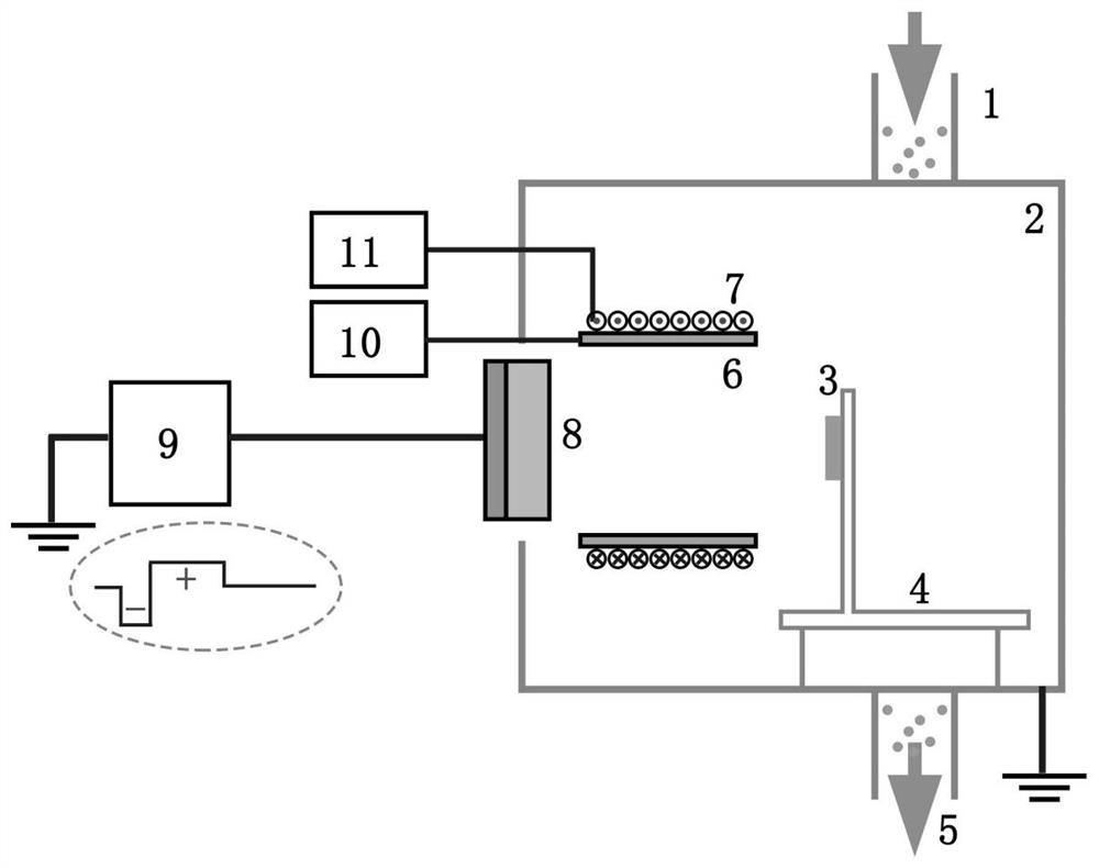
[0038] Step 1: Select an auxiliary anode of appropriate size, shape, and material, and an external magnetic field component of appropriate size and performance, and install it in front of the cathode target.

[0039] Step 2: Complete the pre-evacuation of the discharge system.

[0040]Step 3: Connect the positive and negative pulse output terminals of the bipolar pulse magnetron sputtering power supply to the cathode target.

[0041] Step 4: Select a DC power supply, or a controllable pulse power supply, or a controllable radio frequency power supply to connect to the auxiliary anode to provide voltage for the auxiliary anode.

[0042] Step 5: Introduce the working gas, adjust the voltage waveform, spatial position, and even the shape of the auxiliary anode, and adjust the position and magnetic field strength of the external magnetic field components to maximize the flow rate of deposited ions.

[0043] In step 1 of the present invention, the auxiliary anode can use conductor...


PUM


Abstract

An electromagnetic field coupled bipolar pulse magnetron sputtering system and a method for increasing flow and energy. The system comprises a bipolar pulse magnetron sputtering power supply and a sputtering target, and at least comprises one of an auxiliary anode and an external magnetic field unit, where a pulse output terminal of the bipolar pulse magnetron sputtering power supply is connected to the sputtering target; when the auxiliary anode is included, the auxiliary anode is arranged in front of the sputtering target; when the auxiliary anode comprises the external magnetic field unit, the external magnetic field unit can be configured on the inner side or the outer side of the auxiliary anode; ions generated by negative pulses are driven to fly away from the area nearby the surface of the sputtering target in a bipolar pulse magnetic control discharge mode; the diffusion of deposited ions is optimized by utilizing an electric field generated by the auxiliary anode; and the transmission of electrons is optimized through external magnetic field configuration, the fluidity of plasma diffusion is enhanced, and then the flow of deposited ions is increased. The system is economical and practical, the magnetron sputtering discharge deposition rate can be increased, and the performance of the thin film is improved.

Description

technical field [0001] The present invention relates to equipment and methods for magnetron sputtering. Background technique [0002] Since the advent of magnetron sputtering, the research on it has been increasing year by year, and has attracted the attention of scholars at home and abroad. This technology is widely used in the field of thin film preparation due to its low-temperature deposition, smooth surface, and no particle defects. ), resulting in poor controllability and difficulty in optimizing the quality and performance of the deposited film. In response to this problem, foreign scholars have developed a high-power pulsed magnetron sputtering technology. The peak power during the discharge process can exceed 2 orders of magnitude of ordinary magnetron sputtering, reaching 10kw / cm2, and the electron density around the target can reach 1019 / m3, and the ionization rate of the sputtered material can reach more than 90%, which makes this technology attract great atten...

Claims


Application Information

Patent Timeline
IPC IPC(8): C23C14/35C23C14/56C23C14/54
CPCC23C14/35C23C14/56C23C14/54
Inventor 李刘合韩明月罗阳朱祥瑞李多铎徐晔罗斯达彭徽
Owner BEIHANG UNIV
Learn More