Rubber ring film winding machine

A film winding and apron technology, applied in the direction of external support, packaging, packaging material feeding device, etc., can solve the problems of low work efficiency, heavy labor, time-consuming and laborious, etc., and achieve the effect of improving the work efficiency of film winding

Inactive Publication Date: 2022-02-11
安徽兰翔纺机科技有限公司
View PDF0 Cites 0 Cited by
  • Summary
  • Abstract
  • Description
  • Claims
  • Application Information

AI Technical Summary

Problems solved by technology

[0003] At present, when winding the apron, the mandrel with the apron is usually fixed at the designated working position, and then the film is manually wound, which is labor intensive, time-consuming and laborious, and the work efficiency is low.

Method used


Image

  • Rubber ring film winding machine
  • Rubber ring film winding machine
  • Rubber ring film winding machine

Examples


Embodiment 1

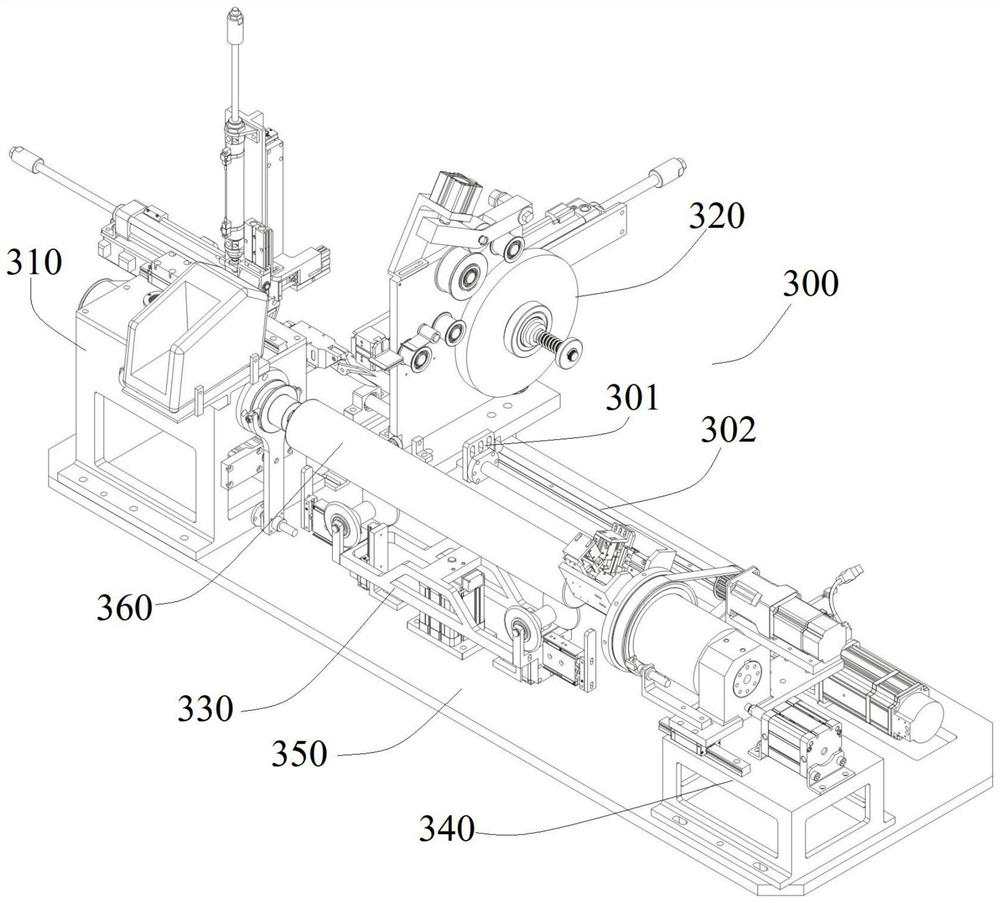
[0066] like Figure 1-27 As shown, the present embodiment provides an apron winding machine 300, comprising:

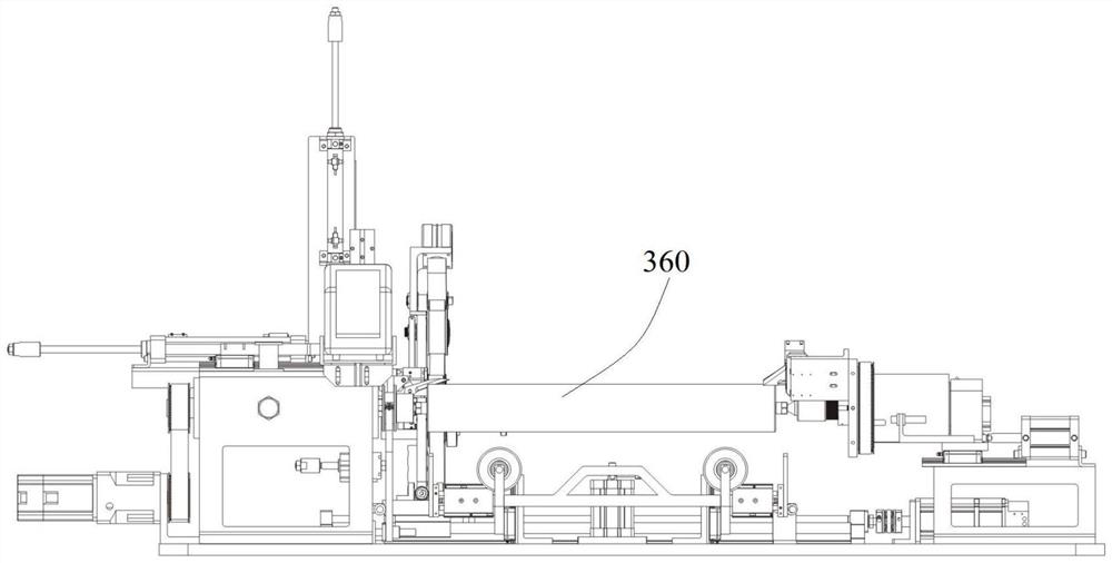
[0067] Lifting device 330, the lifting device 330 can carry the apron 360 to be processed, and drive the apron 360 to be processed up and down, the apron 360 to be processed is set on the mandrel, and the mandrel can be installed on the lifting device 330;

[0068] The back seat box device 340, the back seat box device 340 is located at one end of the lifting device 330, the back seat box device 340 can fix one end of the mandrel, and can compress the film on the starting end of the rubber ring 360 to be processed;

[0069] The headstock device 310, the headstock device 310 is located at the other end of the lifting device 330, the headstock device 310 can fix the other end of the mandrel, and can cut off the film at the end of the apron 360 to be processed;

[0070] The film winding device 320, the film winding device 320 can wind the film on the apron 360 to be pro...

Embodiment 2

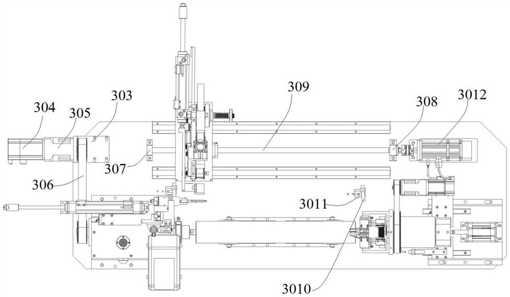
[0108] This embodiment is an improvement made on the basis of Embodiment 1, and its improvements are as follows:

[0109] In this embodiment, a tape machine 311 is also installed on the spindle housing 221, and a tape pressing wheel device is also installed on the spindle housing 221, and the tape pressing wheel device can press the tape on the end of the apron 360 to be processed. , to fix the membrane;

[0110] The tape pressing wheel device includes front and rear drive cylinders 3111, up and down drive cylinders 3114 and left and right drive cylinders 315, front and rear drive cylinders 3111 are installed on the main shaft casing 221, and are arranged parallel to the main shaft 2217; front and rear drive cylinders 3111 are equipped with up and down drive cylinders Support, the upper and lower driving cylinders 3114 are vertically arranged on the upper and lower driving cylinder brackets, the left and right driving cylinder brackets are installed on the upper and lower driv...


PUM


Abstract

The invention discloses a rubber ring film winding machine, and relates to the technical field of rubber ring production. The rubber ring film winding machine comprises a lifting device which can bear a to-be-processed rubber ring and drive the to-be-processed rubber ring to lift, the to-be-processed rubber ring is sleeved on a core rod, and the core rod can be installed on the lifting device; a rear seat box device is located at one end of the lifting device and can abut against one end of the core rod and press the film to the starting end of the rubber ring to be processed. A spindle box device is located at the other end of the lifting device, can clamp the other end of the core rod and can cut off the film at the tail end of the rubber ring to be processed; a film winding device can wind the film on the rubber ring to be processed, and the film winding device can move in the direction from the rear seat box device to the spindle box device; and a control device is used for controlling all the devices. Automatic film winding of the rubber ring can be achieved, time and labor are saved, and the working efficiency of film winding is improved.

Description

technical field [0001] The invention relates to the technical field of apron production, in particular to an apron film winding machine. Background technique [0002] The apron is a commonly used rubber accessory, which is widely used in the textile machines of modern machinery. In the prior art, in the production process of the apron, it is usually necessary to wind the apron, cut, film, vulcanize, Processes such as stripping and external surface grinding to meet subsequent use requirements. [0003] At present, when winding the apron, the mandrel with the apron is usually fixed at a designated working position, and then the film is manually wound, which is labor intensive, time-consuming and laborious, and the work efficiency is low. [0004] Therefore, it is urgent to provide a new rubber ring film winding machine to solve the above-mentioned problems existing in the prior art. Contents of the invention [0005] The object of the present invention is to provide an apr...

Claims


Application Information

Patent Timeline
IPC IPC(8): B65B61/06B65B11/28B65B41/16B65B57/02
CPCB65B61/06B65B11/28B65B41/16B65B57/02
Inventor 卓理财孙元彬赵威陈弋江张超
Owner 安徽兰翔纺机科技有限公司
Why Eureka
Try Eureka