Liftable nursing cart for breast surgery department
A breast surgery and trolley technology, which is applied to trolleys, nursing facilities, surgical equipment, etc., can solve the problems of overweight nursing trolleys, increase the difficulty of medical staff's work, and time-consuming and laborious movement, and achieve the effect of avoiding collisions
- Summary
- Abstract
- Description
- Claims
- Application Information
AI Technical Summary
Problems solved by technology
Method used
Image
Examples
Embodiment 1
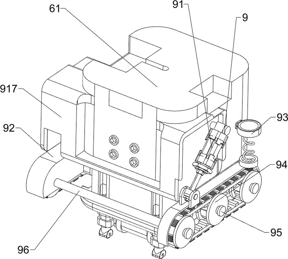
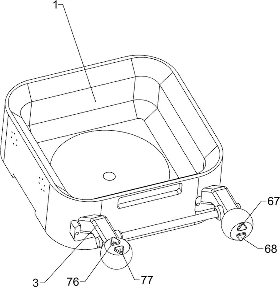
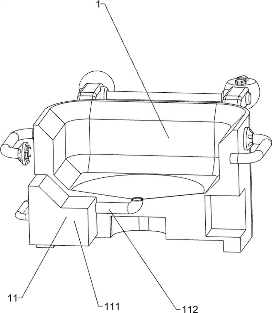
[0038] A kind of liftable nursing trolley for mammary gland surgery department, such as Figure 1-Figure 5Shown, include cart frame 1, storage box 2, cart armrest 3, lifting armrest 4, lifting mechanism 6 and driving mechanism 7, the upper left side of cart frame 1 is fixedly connected with storage box 2, pushes The upper side of the right part of the vehicle frame 1 is provided with a cart handrail 3, and the upper and lower sides of the cart frame 1 are fixedly connected with lifting handrails 4. The cart frame 1 is provided with a lifting mechanism 6, and the lifting mechanism 6 is provided with a driving mechanism 7. .
[0039] The lifting mechanism 6 includes a lifting base 61, a support column 62, a lifting push rod 63, a positioning column 64, a buffer pulley 65, an auxiliary support wheel 66, an ascending button 67 and a descending button 68, and the cart frame 1 is slidably equipped with a lifting base 61 , the lifting base 61 is provided with support columns 62 at i...
Embodiment 2
[0043] On the basis of Example 1, such as Figure 6-Figure 11 As shown, steering mechanism 8 is also included, and steering mechanism 8 includes movable grip sleeve 81, second bevel gear assembly 82, vertical transmission shaft 83, second transmission assembly 84, telescopic rotating shaft 85 and steering wheel 86, pushes Vehicle frame 1 outer surface top rotating type is provided with vertical transmission shaft 83, and cart armrest 3 circles upwards and forwards and backwards symmetrical rotation type is provided with movable grip sleeve 81, front and back both sides movable grip sleeve 81 inboard circumferential direction and vertical transmission shaft 83 tops A second bevel gear assembly 82 is connected between the circumferential direction, and a telescopic rotating shaft 85 is rotatably provided between the right part of the cart frame 1 and the right part of the lifting base 61, and the upper circumferential direction of the telescopic rotating shaft 85 and the lower ci...
Embodiment 3
[0048] On the basis of embodiment 1 and embodiment 2, such as Figure 12-Figure 16As shown, an anti-collision mechanism 10 is also included. The anti-collision mechanism 10 includes a first fixed rack 101, a positioning guide post 102, a buffer spring 103, a second fixed rack 104 and a reversing gear 105. The lower part is embedded with a first fixed rack 101 at intervals, and the top of the cart frame 1 is provided with positioning guide posts 102 at intervals. The positioning guide posts 102 are slidably matched with the positioning post 64. A buffer spring 103 is arranged between them, a second fixed rack 104 is arranged on the outer surface of the positioning column 64, and a reversing gear 105 is arranged on the lower part of the trolley frame 1, and the reversing gear 105 meshes with the first fixed rack 101. The reversing gear 105 meshes with the second fixed rack 104 .
[0049] Also includes a liquid storage mechanism 11, the liquid storage mechanism 11 includes a liq...
PUM
 Abstract
Description
Claims
Application Information
 - R&D
- Intellectual Property
- Life Sciences
- Materials
- Tech Scout
- Unparalleled Data Quality
- Higher Quality Content
- 60% Fewer Hallucinations
Browse by: Latest US Patents, China's latest patents, Technical Efficacy Thesaurus, Application Domain, Technology Topic, Popular Technical Reports.
© 2025 PatSnap. All rights reserved.Legal|Privacy policy|Modern Slavery Act Transparency Statement|Sitemap|About US| Contact US: help@patsnap.com


