Remote pupil observation device for critical patient
An observation device and pupil technology, which is applied in the field of remote pupil observation devices for critically ill patients, can solve problems such as unfavorable efficiency, time-consuming, eyes cannot be opened consciously, etc., and achieve the effect of solving inconvenience and reducing work intensity
- Summary
- Abstract
- Description
- Claims
- Application Information
AI Technical Summary
Problems solved by technology
Method used
Image
Examples
Embodiment 1
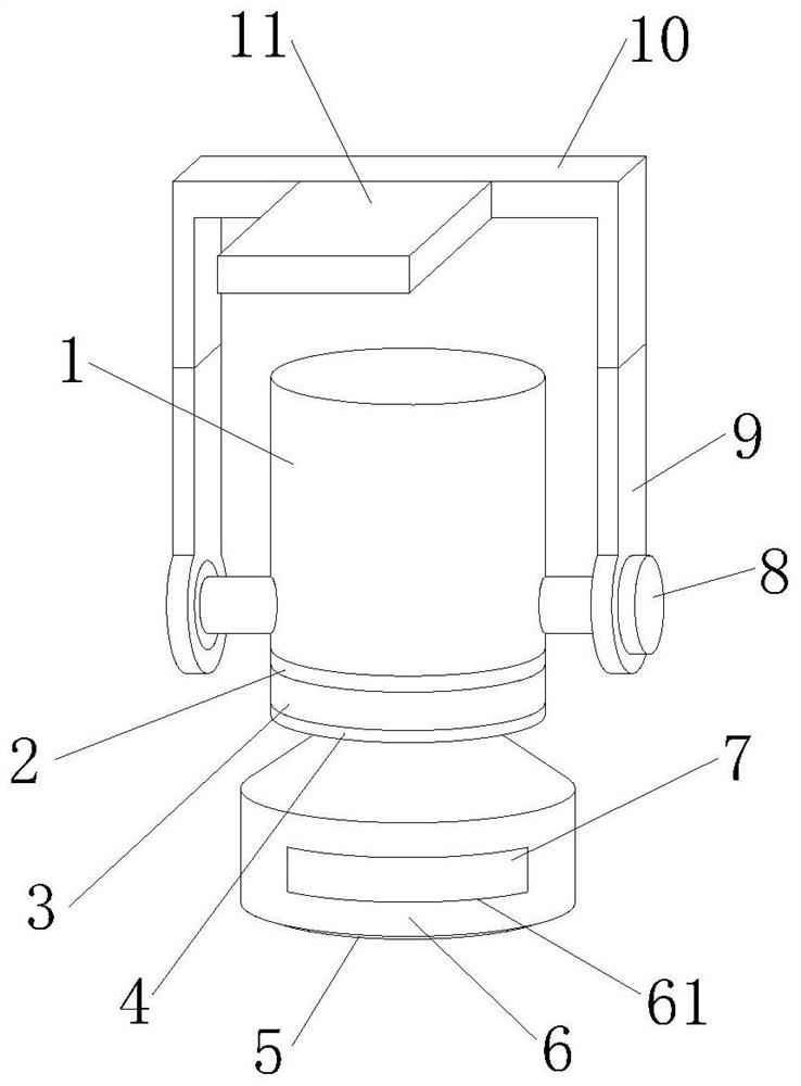
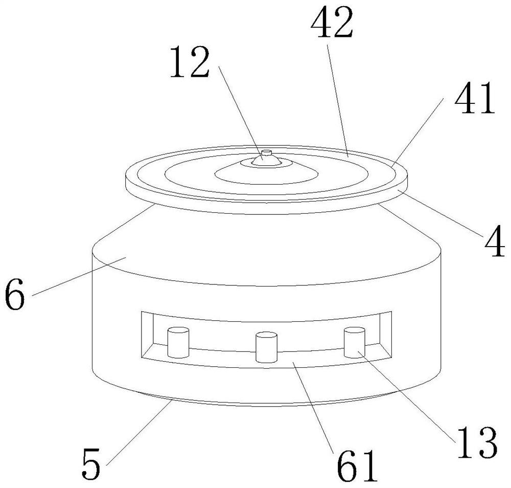
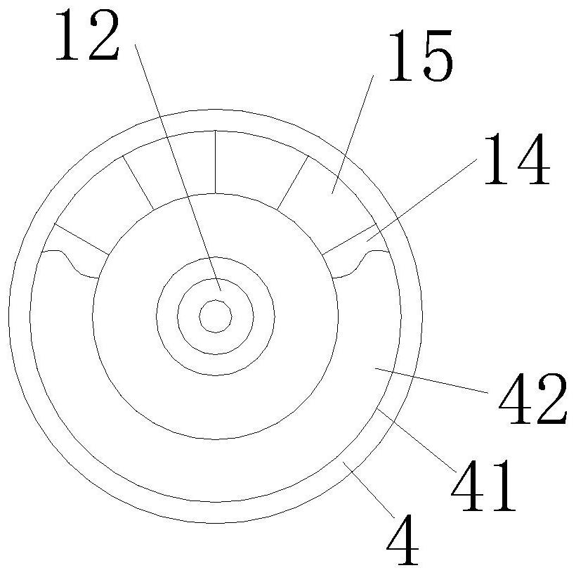
[0033] like Figure 1-3 As shown, a remote pupil observation device for critically ill patients includes an upper disc 2, a lower disc 4, an eye-shaped silicone strip 5, a goggle 6, an arc-shaped iron core 14, an arc-shaped electromagnet 15, and an eyelid paste Assembly 16, camera 18, shadowless lamp group 20, pupil capture camera 21, and push-pull sheet 23, balls 12 are installed at the middle of the bottom of the upper disk 2, and the balls 12 are rolled and engaged in the joint groove structure at the middle of the top of the lower disk 4 , the top surface of the lower disc 4 is provided with a ring groove 41, and the arc-shaped iron core 14 and the arc-shaped electromagnet 15 are alternately installed in the ring groove 41, and the top end surface of the eye protection tube 6 is connected to the bottom of the lower disc 4. It is fixedly connected, and both sides in the elliptical cylinder mouth of eye protection tube 6 are all equipped with corner-of-the-eye type connectio...
Embodiment 2
[0036] like Figure 4 , 5 As shown in and 7, the same ends of the two eye-shaped silica gel bars 5 are connected to each other through the corner-shaped connection software 17 at both ends, and eyelids are arranged in the arc groove 51 on the eye-shaped silica gel bars 5. Sticking assembly 16, the inner edge of the eye-shaped silicone strip 5 is connected to the outer edge of the push-pull sheet 23, and the inner edge of the push-pull sheet 23 is connected to the push rod ends of the three first cylinders 13 of the same group in sequence;
[0037]Described eyelid sticking assembly 16 comprises tearable paper 161, eyelid sticky paper 162, arc-shaped sticky tape 163 and arc-shaped buckle 164, and arc-shaped sticky buckle 164 is installed in the groove bottom of arc-shaped groove 51, and eyelid sticky paper 162 outer surface Be located at tear-off paper 161, and arc adhesive tape 163 is installed on the back side of eyelid adhesive paper 162, arc adhesive tape 163 is bonded and ...
Embodiment 3
[0040] like Figure 4 , 5 As shown in and 7, the same ends of the two eye-shaped silica gel bars 5 are connected to each other through the corner-shaped connection software 17 at both ends, and eyelids are arranged in the arc groove 51 on the eye-shaped silica gel bars 5. Sticking assembly 16, the inner edge of the eye-shaped silicone strip 5 is connected to the outer edge of the push-pull sheet 23, and the inner edge of the push-pull sheet 23 is connected to the push rod ends of the three first cylinders 13 of the same group in sequence;
[0041] Described eyelid sticking assembly 16 comprises tearable paper 161, eyelid sticky paper 162, arc-shaped sticky tape 163 and arc-shaped buckle 164, and arc-shaped sticky buckle 164 is installed in the groove bottom of arc-shaped groove 51, and eyelid sticky paper 162 outer surface Be located at tear-off paper 161, and arc adhesive tape 163 is installed on the back side of eyelid adhesive paper 162, arc adhesive tape 163 is bonded and...
PUM
 Abstract
Description
Claims
Application Information
 - R&D
- Intellectual Property
- Life Sciences
- Materials
- Tech Scout
- Unparalleled Data Quality
- Higher Quality Content
- 60% Fewer Hallucinations
Browse by: Latest US Patents, China's latest patents, Technical Efficacy Thesaurus, Application Domain, Technology Topic, Popular Technical Reports.
© 2025 PatSnap. All rights reserved.Legal|Privacy policy|Modern Slavery Act Transparency Statement|Sitemap|About US| Contact US: help@patsnap.com


