
Hydraulic gas compressor

A gas compressor, hydraulic technology, applied in liquid variable capacity machinery, machines/engines, mechanical equipment, etc., can solve the problems of decreased energy efficiency, overloaded operation of supporting motors, damage to pump accessories, etc. Save energy, improve ease of installation and movement, and reduce footprint

Pending Publication Date: 2022-02-08
朱学斌
View PDF1 Cites 0 Cited by
  • Summary
  • Abstract
  • Description
  • Claims
  • Application Information

AI Technical Summary

Problems solved by technology

However, there are still some serious disadvantages in the use of hydraulic air compressors with centrifugal liquid booster pumps, and corresponding measures need to be taken to address the disadvantages
Specifically: the efficiency and stability of the centrifugal liquid pressurized pump is only near its design flow and design head conditions. If the working conditions deviate from the design flow and design head conditions, the efficiency of energy use will be greatly reduced, and the low output resistance will lead to a large output flow. , The supporting motor may be overloaded, the cavitation phenomenon in the pump will damage the accessories in the pump, and the cavitation phenomenon will cause loud noise

Method used


Image

  • Hydraulic gas compressor
  • Hydraulic gas compressor

Examples


Embodiment

[0027] Such as figure 1 As shown, a hydraulic gas compressor mainly includes a tank A 4 , a tank B 15 and a two-way liquid booster pump 2 . The lower parts of tank A 4 and tank B 5 are filled with liquid, and the top of the liquid is filled with air. The bottom of A tank 4 is provided with A tank liquid inlet and outlet pipe 1, and the top of A tank 4 is provided with A tank outlet valve 7, and A tank 4 is provided with A tank inlet valve 6. The bottom of the B tank 15 is provided with a B tank liquid inlet and outlet pipe 17, and the top of the B tank 15 is provided with a B tank gas outlet valve 12, and the B tank 15 is provided with a B tank inlet valve 13. Both ends of the two-way liquid pressurizing pump 2 are respectively connected with the liquid inlet and outlet pipe 1 of tank A and the liquid inlet and outlet pipe 17 of tank B.

[0028] working principle:

[0029] The process in which tank A liquid 3 is injected into tank B 15 under pressure (referred to as the pos...


PUM


Abstract

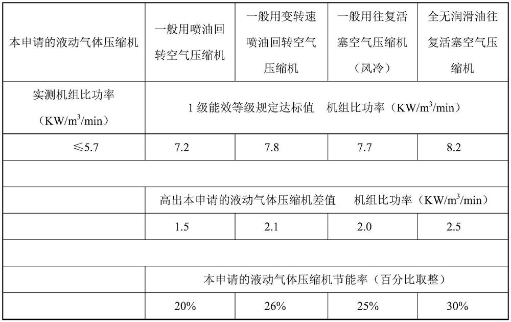
The invention discloses a hydraulic gas compressor. The hydraulic gas compressor comprises a tank A, a tank B and a two-way liquid pressure pump; the lower parts of the tank A and the tank B are filled with liquid; a tank A liquid inflow and outflow pipe is arranged at the lower part of the tank A, a tank A air outlet valve is arranged at the upper part of the tank A, and a tank A air inlet valve is arranged on the tank A; a tank B liquid inflow and outflow pipe is arranged at the lower part of the tank B, a tank B air outlet valve is arranged at the upper part of the tank B, a tank B air inlet valve is arranged on the tank B; and two ends of the liquid pressure pump are respectively connected with the A tank liquid inflow and outflow pipe and the B tank liquid inflow and outflow pipe. According to the hydraulic gas compressor, high-pressure liquid is used for compressing air. Compared with a traditional air compressor, the hydraulic gas compressor has the advantages of highenergy utilization efficiency and low noise and can generate pure compressed air free of oil pollution; the energy efficiency of thehydraulic gas compressor is higher than the standard value specified by an optimal machine type in the national standard and reach 20%, and the energy efficiency can reach 30% in a special application occasion free of oil pollution gas, and thus, great contribution can be made to energy conservation and emission reduction in the world.

Description

technical field [0001] The invention relates to the field of gas compression equipment, in particular to a hydraulic gas compressor. Background technique [0002] Gas compressors are widely used in the fields of gas storage, transportation and manufacturing. There are four commonly used reciprocating piston compressors, oil-injected screw compressors, oil-injected scroll compressors, and oil-injected sliding vane compressors. Most of them are driven by electric motors such as pistons or screws to directly compress gas, all of which have low energy efficiency and Noisy commonality. [0003] The uncommonly used hydraulic air compressor (patent number: ZL 200720149117.1) has high energy efficiency and low noise, but it needs a liquid storage tank to use it, resulting in high cost, large floor space, and inconvenient installation. The cost of moving, installation, and moving is high. During the process of draining and inhaling, the liquid in the cylinder uses the potential ene...

Claims


Application Information

Patent Timeline
Patent Type & Authority Applications(China)
IPC IPC(8): F04B35/02
CPCF04B35/00
Inventor 朱学斌
Owner 朱学斌
Learn More