Jet water-saving irrigation equipment with quantitative and constant-pressure functions
A technology of equipment and functions, applied in the field of spray water-saving irrigation equipment, can solve the problems of constant pressure and quantitative output of difficult water solution, adjustment of sprinkler irrigation angle, poor use effect, etc. The effect of improving usability
- Summary
- Abstract
- Description
- Claims
- Application Information
AI Technical Summary
Problems solved by technology
Method used
Image
Examples
Embodiment 1
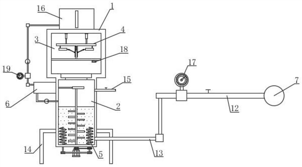
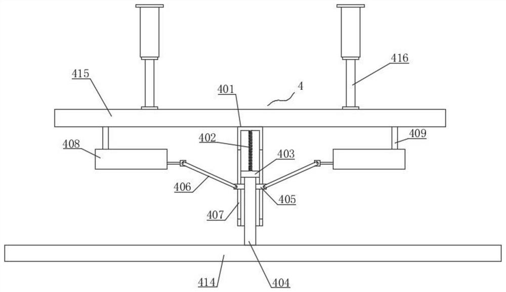
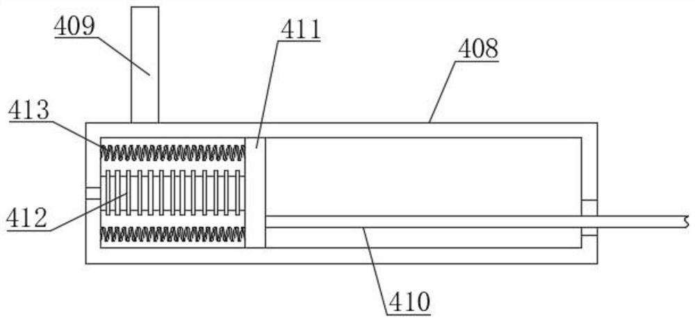
[0053] Such as Figure 1-11 As shown, the present invention proposes a spray water-saving irrigation equipment with quantitative and constant pressure functions, comprising a water storage tank 1, the bottom of the water storage tank 1 is fixed with a bracket 14 by bolts, and a water storage chamber 2 is provided in the water storage tank 1. The water supply pipe 15 is installed on the water storage tank 1 and communicates with the water storage chamber 2, and a valve is installed on the water supply pipe 15, and a liquid level sensor is installed in the water storage chamber 2, and the liquid level sensor monitors the liquid level in the water storage chamber 2. For real-time detection, the water storage tank 1 is provided with a plenum chamber 3, the plenum chamber 3 is located above the water storage chamber 2, and the plenum chamber 3 is equipped with a voltage regulator assembly 4, and the pressure regulator assembly 4 is equipped with an air pressure sensor 18, The air p...
Embodiment 2
[0062] Such as figure 1 and Figure 12 As shown, the difference between this embodiment and Embodiment 1 is that an automatic infusion assembly 6 is installed on the water storage tank 1, and the top of the water storage tank 1 is fixed with a liquid storage tank 16 by bolts, and the automatic infusion assembly 6 includes a sealed transfer box 61, The sealed transfer case 61 is fixedly installed on the water storage tank 1 by bolts, the liquid inlet pipe 68 and the liquid outlet pipe 69 are installed on the sealed transfer case 61, and the end of the liquid inlet pipe 68 away from the sealed transfer case 61 communicates with the liquid storage tank 16, One end of the liquid outlet pipe 69 away from the sealed transfer box 61 communicates with the water storage chamber 2, and a one-way valve is installed on the liquid inlet pipe 68 and the liquid outlet pipe 69, and the one-way valve on the liquid inlet pipe 68 makes the liquid flow from the liquid storage tank. 16 unidirecti...
Embodiment 3
[0065] Such as figure 1 , Figure 13 and Figure 14 As shown, the difference between this embodiment and Embodiment 1 and Embodiment 2 is that a stirring assembly 5 is installed in the water storage chamber 2, and the stirring assembly 5 includes a driving motor 51, and the driving motor 51 is fixedly installed in the water storage tank through a motor base. 1, the output end of the drive motor 51 is equipped with a drive shaft 52, and the drive shaft 52 extends upwards into the water storage chamber 2; the number of stirring rods 53 is multiple groups, and the stirring rods 53 are connected with the drive shaft 52 and located in the storage chamber. In the water chamber 2, the number of vertical rods 54 is multiple groups and distributed in an annular array around the driving shaft 52. The helical blade 55 is arranged on the vertical rods 54 and is located in the water storage chamber 2. The driving shaft 52 passes through the first transmission belt 56 and the A group of v...
PUM
 Abstract
Description
Claims
Application Information
 - Generate Ideas
- Intellectual Property
- Life Sciences
- Materials
- Tech Scout
- Unparalleled Data Quality
- Higher Quality Content
- 60% Fewer Hallucinations
Browse by: Latest US Patents, China's latest patents, Technical Efficacy Thesaurus, Application Domain, Technology Topic, Popular Technical Reports.
© 2025 PatSnap. All rights reserved.Legal|Privacy policy|Modern Slavery Act Transparency Statement|Sitemap|About US| Contact US: help@patsnap.com


