Exhaust gas aftertreatment device

A technology of exhaust post-treatment and equipment, which is applied in the direction of exhaust treatment, mechanical equipment, exhaust devices, etc. It can solve the problems of inability to ensure exhaust post-treatment and the limitation of predetermined structural space, etc., to achieve improved particle separation, Effect of High Discharge Temperature

Pending Publication Date: 2022-02-01
CPT GRP GMBH
View PDF3 Cites 0 Cited by
  • Summary
  • Abstract
  • Description
  • Claims
  • Application Information

AI Technical Summary

Problems solved by technology

[0007] Especially in the case of ever-increasing demands on exhaust gas aftertreatment and increasingly restricted installation space specified by manufacturers, it is increasingly necessary to arrange all the components required for extremely effective exhaust gas aftertreatment. big challenge
[0008] Disadvantages of the devices of the prior art are in particular that optimal exhaust gas aftertreatment cannot be ensured when a particulate filter is required in addition to a catalytic converter and when the available installation space, in particular the installation length, is small

Method used


Image

  • Exhaust gas aftertreatment device

Examples


Embodiment Construction

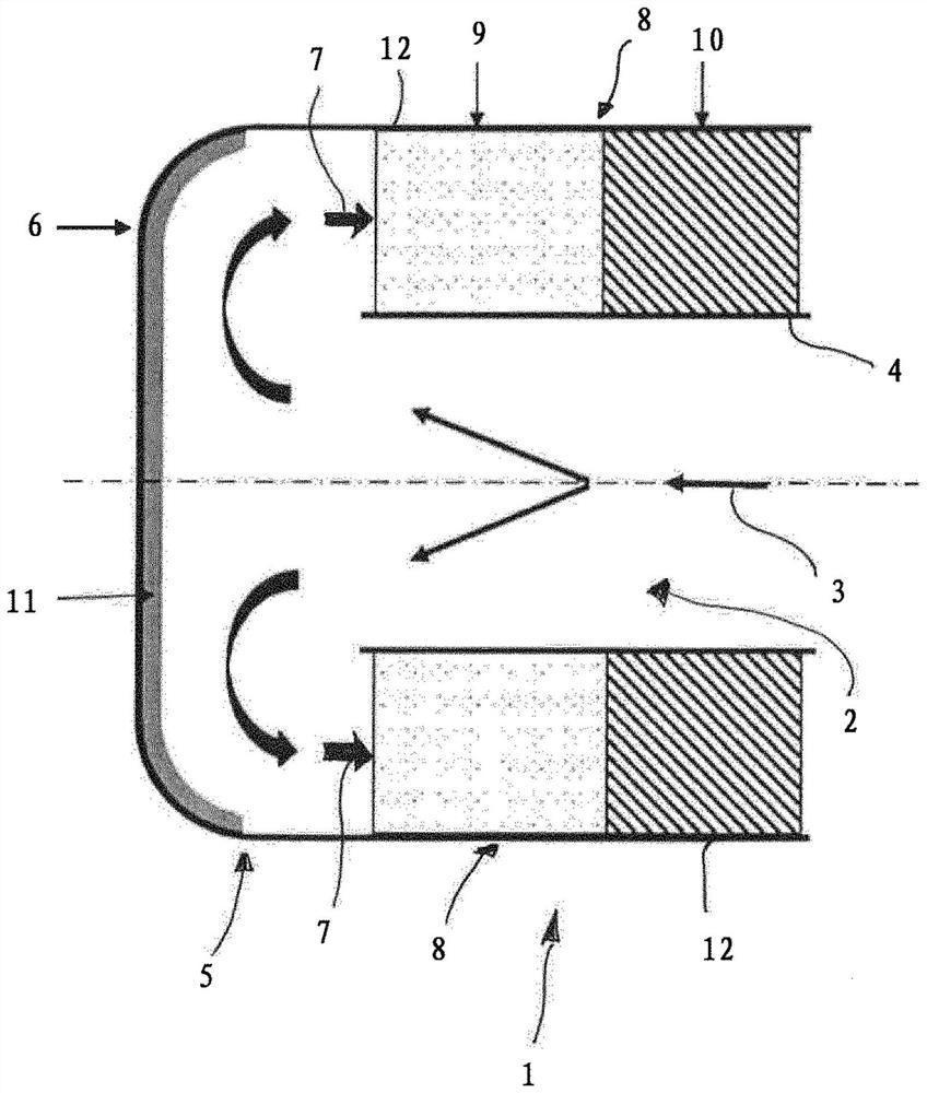
[0027] figure 1 An annular catalytic converter 1 is shown. The annular catalytic converter has a centrally located first tubular flow section 2 through which exhaust gas can flow in flow direction 3 . The tubular flow section 2 is bounded in the radial direction by an inner tube 4 . A deflection region 5 is arranged downstream of the tubular flow section 2 in the flow direction 3 .

[0028] The diversion area 5 is formed by a cover element 6 onto which the exhaust gas flowing through the tubular flow section 2 flows. By impinging on the cover element 6 , the exhaust gas is deflected radially outwards and finally in a flow direction 7 , which is 180° opposite to the flow direction 3 .

[0029] The exhaust gas then flows through the second annular flow section 8 through a plurality of elements for exhaust gas aftertreatment arranged in this flow section 8 . exist figure 1 shows an annular catalytic converter 9 which, for example, has a catalytically active coating in order ...


PUM


Abstract

The invention relates to an exhaust gas aftertreatment device. The device comprises a first tubular flow section (2), a deflecting region (5), and a second annular flow section (8). The tubular flow section (2) is formed by an inner tube (4), and the annular flow section (8) is formed by an outer tube (12), which runs substantially parallel to the inner tube (4), so as to run between the inner tube (4) and the outer tube (12). The deflecting region (5) is designed to deflect the exhaust gas flow from the tubular flow section (2) into the annular flow section (8), and the device has an annular catalytically active carrier (9) and an annular particle filter (10), wherein the carrier (9) and the particle filter (10) are arranged in the annular flow section (8).

Description

technical field [0001] The invention relates to a device for aftertreatment of exhaust gases with a first tubular flow section, a diversion region and a second annular flow section, wherein the tubular flow section is formed by an inner tube and the annular flow section is formed by an essentially parallel inner The outer tube of the tube extension is formed between the inner tube and the outer tube, and the deflection region is designed to deflect the exhaust gas flow from the tubular flow path into the annular flow path. Background technique [0002] For the exhaust gas aftertreatment of the exhaust gas of internal combustion engines, catalytic converters are used in particular, which are able to convert the exhaust gas components into less harmful substances. For this purpose, catalytic converters are known with different designs and dimensions. [0003] Furthermore, so-called annular catalytic converters are known which have a tubular flow section followed by a flow def...

Claims


Application Information

Patent Timeline
Patent Type & Authority Applications(China)
IPC IPC(8): F01N3/021F01N3/20F01N13/00
CPCF01N3/021F01N3/20F01N13/0097F01N2250/02F01N2470/24F01N2470/22Y02T10/12F01N3/035F01N3/2892F01N2240/20
Inventor R·布鲁克P·希尔特S·舍佩尔斯D·奥登塔尔
Owner CPT GRP GMBH
Why Eureka
Try Eureka