
Rotor structure and ultra-low vibration noise permanent magnet motor

A technology of rotor structure and rotating shaft, applied in synchronous motors with static armatures and rotating magnets, magnetic circuit rotating parts, magnetic circuit shape/style/structure, etc., can solve the problem of no ideal ultra-low vibration noise permanent magnet Motor and other problems, to achieve the effect of reducing electromagnetic vibration and torque fluctuation, reducing vibration and noise, and reducing electromagnetic radial components

Inactive Publication Date: 2022-02-01
苏州保邦电气有限公司
View PDF7 Cites 0 Cited by
  • Summary
  • Abstract
  • Description
  • Claims
  • Application Information

AI Technical Summary

Problems solved by technology

[0004] The purpose of the present invention is to provide a rotor structure and an ultra-low vibration and noise permanent magnet motor to solve the problem that there is no ideal ultra-low vibration and noise permanent magnet motor

Method used


Image

  • Rotor structure and ultra-low vibration noise permanent magnet motor
  • Rotor structure and ultra-low vibration noise permanent magnet motor
  • Rotor structure and ultra-low vibration noise permanent magnet motor

Examples


Embodiment Construction

[0035] The present invention will be further described in detail below in conjunction with the accompanying drawings and embodiments. It should be understood that the specific embodiments described here are only used to explain the present invention, but not to limit the present invention. In addition, it should be noted that, for the convenience of description, only some structures related to the present invention are shown in the drawings but not all structures.

[0036] In the description of the present invention, unless otherwise clearly specified and limited, the terms "connected", "connected" and "fixed" should be understood in a broad sense, for example, it can be a fixed connection, a detachable connection, or an integrated ; It can be a mechanical connection or an electrical connection; it can be a direct connection or an indirect connection through an intermediary, and it can be the internal communication of two components or the interaction relationship between two ...


PUM


Abstract

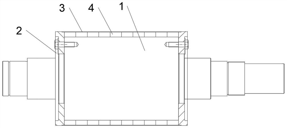
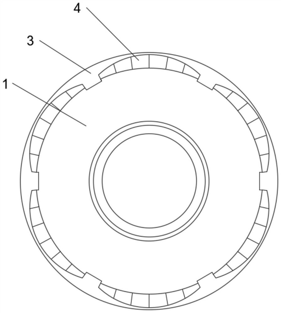
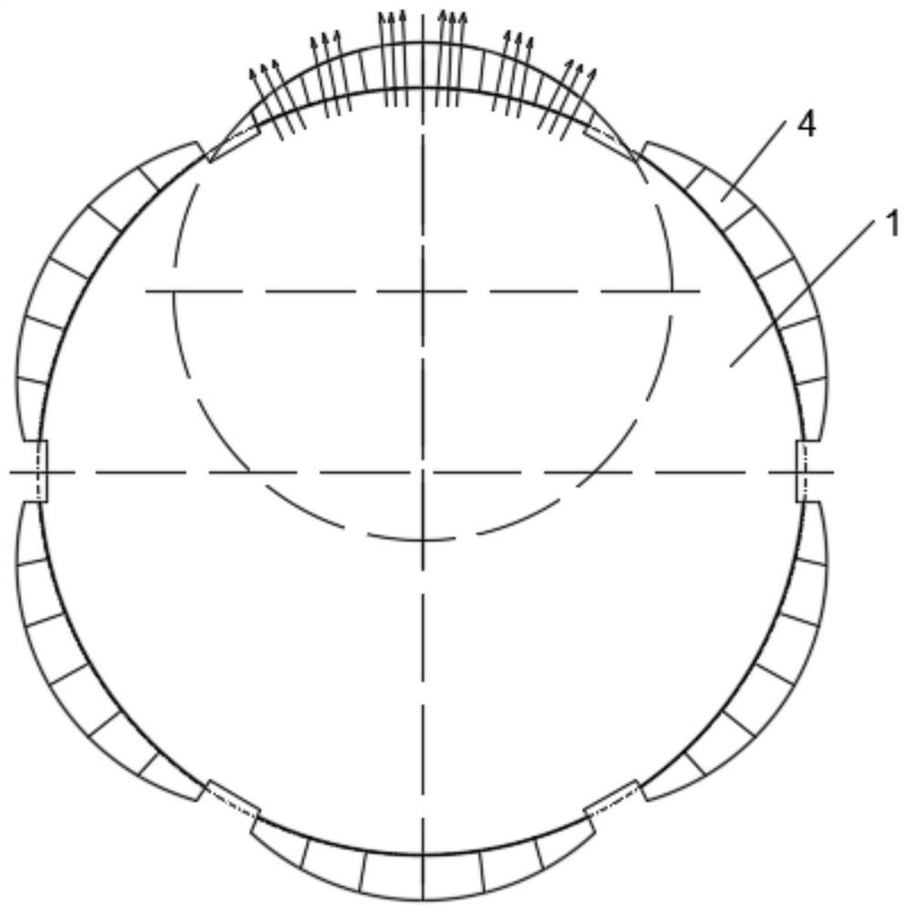
The invention discloses a rotor structure and an ultra-low vibration noise permanent magnet motor, the rotor structure comprises a rotating shaft, two end plates, a plurality of pressing plates and a plurality of pieces of magnetic steel, the two end plates are spaced along the axial direction of the rotating shaft and are fixedly connected to the rotating shaft, and the plurality of pressing plates are sequentially and fixedly connected to the rotating shaft along the circumferential direction of the rotating shaft. A containing cavity is formed between every two adjacent pressing plates and the rotating shaft, the multiple pieces of magnetic steel are located between the two end plates, and the multiple pieces of magnetic steel are fixedly arranged in the multiple containing cavities in a one-to-one correspondence mode. Each piece of magnetic steel is provided with a first surface and a second surface which are oppositely arranged, the first surface and the second surface are arc-shaped, and a circle where the first surface is located and a circle where the second surface is located are eccentrically arranged; Each piece of magnetic steel comprises a plurality of magnetic steel blocks, the magnetic steel blocks are distributed in an array mode, m rows of magnetic steel blocks are arranged in the circumferential direction of the rotating shaft, n columns of magnetic steel blocks are arranged in the axial direction of the rotating shaft, and m and n are both integers larger than 1. The rotor structure can simulate an ideal magnetic field, and the electromagnetic radial component is reduced by optimizing the sine electromagnetic exciting force so as to reduce vibration and noise.

Description

technical field [0001] The invention relates to the technical field of motors, in particular to a rotor structure and an ultra-low vibration and noise permanent magnet motor. Background technique [0002] The low vibration and noise of the motor refers to the ability of the motor to neither radiate low-frequency magnetic fields to the outside, nor to resist external magnetic field interference such as low magnetic fields, when the motor is in a special working environment. Ultra-low vibration and noise motors have higher requirements on mechanical vibration. [0003] At present, low-vibration and noise motors are generally asynchronous motors. Electromagnetic harmonics are optimized by means of magnetic pole optimization, inclined slots, and reasonable slot matching to weaken electromagnetic excitation force and mechanical vibration. For the permanent magnet synchronous motor, there is a strong electromagnetic attraction between the stator and the rotor. The tangential comp...

Claims


Application Information

Patent Timeline
Patent Type & Authority Applications(China)
IPC IPC(8): H02K1/276H02K1/28H02K21/14
CPCH02K1/276H02K1/28H02K21/14
Inventor 王春彦尚栋黄杰
Owner 苏州保邦电气有限公司
Learn More