Direct current charging connector suitable for large current
A DC charging and connector technology, applied in vehicle connectors, electric vehicle charging technology, connection, etc., can solve the problems of inability to meet creepage distance requirements, inability to ensure safe use, insufficient creepage distance, etc., to improve electrical connection. performance, reduce signal interference, and increase the effect of creepage distance
- Summary
- Abstract
- Description
- Claims
- Application Information
AI Technical Summary
Problems solved by technology
Method used
Image
Examples
Embodiment 1
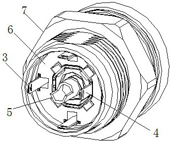
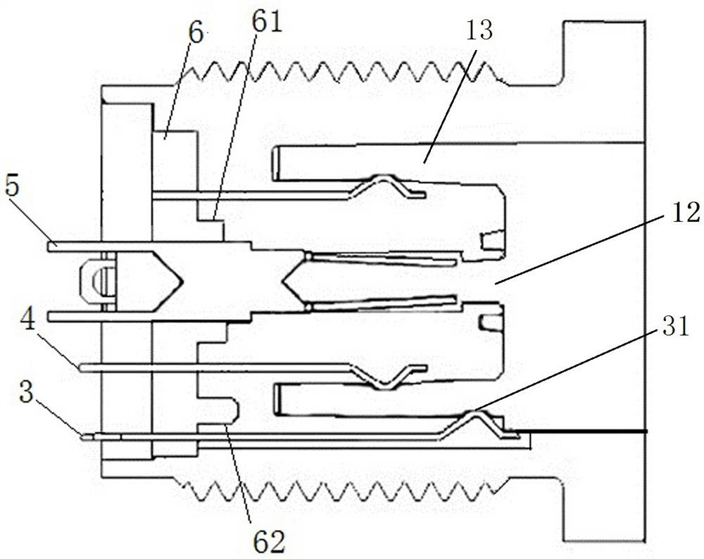
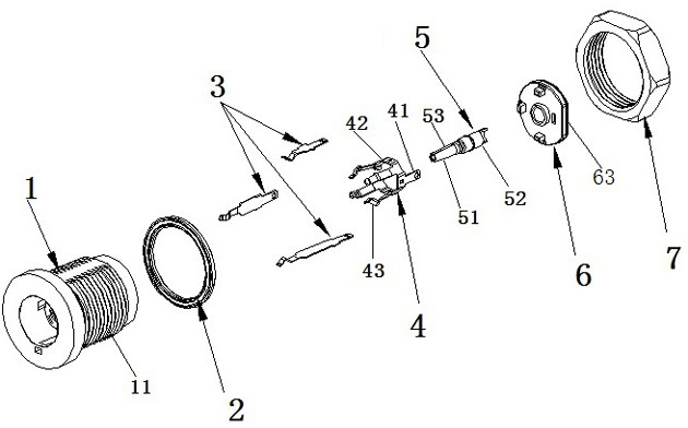
[0037] This embodiment introduces a DC charging connector, combined with Figure 1 to Figure 3 , the DC charging connector includes an insulating body 1 , a positive terminal 5 , a negative terminal 4 and a signal terminal 3 .
[0038] refer to figure 2 As shown, the insulating main body 1 is cylindrical, and its axial center is provided with a first socket 12, and the outer periphery of the first socket is provided with a second socket 13; one end of the positive terminal 5 is penetrated to the first socket In the groove, the other end extends toward the tail end of the insulating body 1 ; the negative terminal 4 is arranged on the outer periphery of the positive terminal 5 , and the signal terminal 3 is penetrated through the peripheral portion of the insulating body 1 .
[0039] The inner ring side wall and the outer ring side wall of the second socket are respectively provided with contact ports corresponding to the negative terminal 4 and the signal terminal 3, and the ...
Embodiment 2
[0049] Considering that the existing high-current chargers still have the defects of high scrap rate of finished products caused by unreasonable space utilization and difficulty in assembly and welding, this embodiment introduces another method that can ensure the effective distance between different types of terminals. Basically, it can also reduce the difficulty of assembly and welding, and make full use of the DC charging connector in the internal space of the connector.
[0050] combine Figure 1 to Figure 5 , on the basis of Example 1, in this example, such as figure 1 As shown, the negative terminal 4 includes a cable connection end 41, an annular connection portion 42 and a plurality of socket terminals 43, one end of the cable connection end is connected to one side of the ring connection portion, and a plurality of socket ends are distributed and connected to the ring connection portion. Perimeter on the other side.
[0051] combine figure 1 and Figure 4 , the ...
PUM
 Abstract
Description
Claims
Application Information
 - R&D
- Intellectual Property
- Life Sciences
- Materials
- Tech Scout
- Unparalleled Data Quality
- Higher Quality Content
- 60% Fewer Hallucinations
Browse by: Latest US Patents, China's latest patents, Technical Efficacy Thesaurus, Application Domain, Technology Topic, Popular Technical Reports.
© 2025 PatSnap. All rights reserved.Legal|Privacy policy|Modern Slavery Act Transparency Statement|Sitemap|About US| Contact US: help@patsnap.com


