
Cable trench cover plate assembly and use method thereof

A cable trench cover and component technology, which is applied to the installation of electrical components, cables, and ground cables, etc., can solve the problems of increasing the risk of cable leakage, difficult work, and increasing the number of staff, so as to reduce the risk of falling into the cable trench Effects that reduce the risk of injury, reduce the chance of being injured, and increase the chance of being injured

Inactive Publication Date: 2022-01-28
王树合
View PDF0 Cites 0 Cited by
  • Summary
  • Abstract
  • Description
  • Claims
  • Application Information

AI Technical Summary

Problems solved by technology

The present invention is mainly used to solve the problem that when installing and overhauling cables in some cable trenches with small spaces at present, it is necessary for workers to lie on the ground and probe their bodies into the cable trenches for operation. This method is difficult to work and increases the number of cables The difficulty of installation and maintenance, it is inconvenient for the staff to install and overhaul the cables, and at the same time, the staff will plunge their bodies into the cable trench, which will increase the chance of the staff falling into the cable trench and increase the chance of the staff being injured, and During the rainy season or when it rains heavily, water is prone to accumulate in the cable trench, making the cables at the lower end of the cable trench easy to be soaked or even submerged by water, which will accelerate the aging of the cable insulator, cause the insulator to rupture, increase the risk of cable leakage, and affect pedestrians and people on the road. vehicle safety issues

Method used


Image

  • Cable trench cover plate assembly and use method thereof
  • Cable trench cover plate assembly and use method thereof
  • Cable trench cover plate assembly and use method thereof

Examples


Embodiment Construction

[0040] In order to make the technical means, creative features, goals and effects achieved by the present invention easy to understand, the present invention will be further described below in conjunction with specific embodiments.

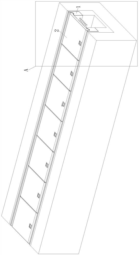
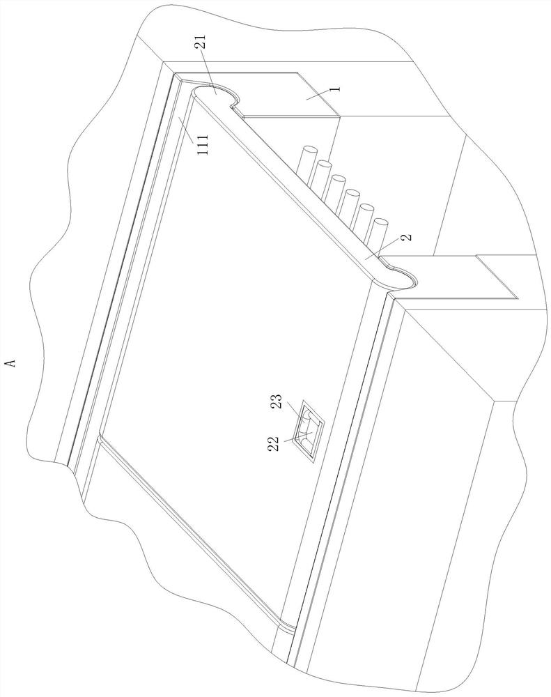
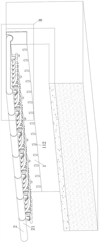
[0041] Such as figure 1 , figure 2 , image 3 , Figure 4 with Figure 10 As shown, a cable trench cover plate assembly includes a support 1, a cover 2 and an installation mechanism 3; the support 1 is symmetrically arranged; the support 1 is poured together with the wall of the cable trench; the support The upper end of the member 1 is provided with the cover member 2; the cover member 2 is evenly spaced; the two ends of the cover member 2 are placed on the upper ends of the two support members 1 respectively; An installation mechanism 3; the installation mechanism 3 is connected to the cover 2; the installation mechanism 3 is used to realize the installation of cables.

[0042] When working, pour the supporting part 1 and the trench wall o...


PUM


Abstract

The invention belongs to the technical field of cable trench accessories, and particularly relates to a cable trench cover plate assembly and a use method thereof. The cable trench cover plate assembly comprises a supporting part, a covering part and a mounting mechanism. By arranging the mounting mechanism, before the covering part is mounted, a cable is mounted on the covering part through the mounting mechanism, so that a worker is prevented from lying on the ground and stretching the body into a cable trench to mount the cable, the risk that the worker falls into the cable trench is reduced, the probability that the worker is injured is reduced, meanwhile, the cable installation difficulty is reduced, and cable installation is facilitated; and the cable is suspended below the covering part, so that the distance between the cable and accumulated water at the bottom of the cable trench is increased, the probability that the cable is soaked by the accumulated water is reduced, the aging of a cable insulator is prevented from being accelerated due to soaking of the cable, the aging speed of the insulator is reduced, the service life of the cable is prolonged, the probability of electric leakage of the cable is reduced, and the safety of pedestrians and vehicles on the road surface is ensured.

Description

technical field [0001] The invention belongs to the technical field of cable trench accessories, in particular to a cable trench cover plate assembly and a method for using the same. Background technique [0002] With the rapid development of the city, the roads, buildings, cables, vegetation and other facilities on the ground are getting older and more, which makes the city look very crowded. At present, many cities build subways and underground pipe corridors to alleviate the congestion on the ground. Therefore, the cable It is also more and more transferred from the ground to the underground cable trench or underground pipeline. During construction, the cable is first hung on the side wall of the cable trench, and the cable trench is covered by the cover plate, so that the cable trench and Space isolation above ground to protect cables in cable trenches. [0003] At present, the cables in the cable trench are basically hung on the side walls of the cable trench. When ins...

Claims


Application Information

Patent Timeline
Patent Type & Authority Applications(China)
IPC IPC(8): H02G9/02H02G9/06
CPCH02G9/025H02G9/06
Inventor 王树合
Owner 王树合
Learn More