Pipeline anti-disengaging connecting assembly

A technology for connecting components and pipes, applied in the direction of pipe/pipe joint/pipe fitting, sleeve/socket connection, through components, etc., can solve the problems of occupation, increase pipe cost, large capital and warehouse space, etc. Reduce maintenance costs and reduce warehouse space

Pending Publication Date: 2022-01-28
SOUTHEAST PIPE VALVE CO LTD
View PDF1 Cites 1 Cited by
  • Summary
  • Abstract
  • Description
  • Claims
  • Application Information

AI Technical Summary

Problems solved by technology

However, since the inner diameters of the bonnet and the elastic metal pressure ring are fixed, when the diameters of the drainage pipes are different, different bonnets and elastic metal pressure rings need to be used. However, it is often difficult for the maintenance personnel of the drainage network to know in advance The diameter of the pipeline to be repaired, therefore, it is usually necessary to back up valve covers and elastic metal pressure rings of various sizes in order to choose according to actual needs, which requires a large amount of capital and warehouse space, which greatly increases the cost of pipeline maintenance

Method used


Image

  • Pipeline anti-disengaging connecting assembly
  • Pipeline anti-disengaging connecting assembly
  • Pipeline anti-disengaging connecting assembly

Examples


Embodiment 1

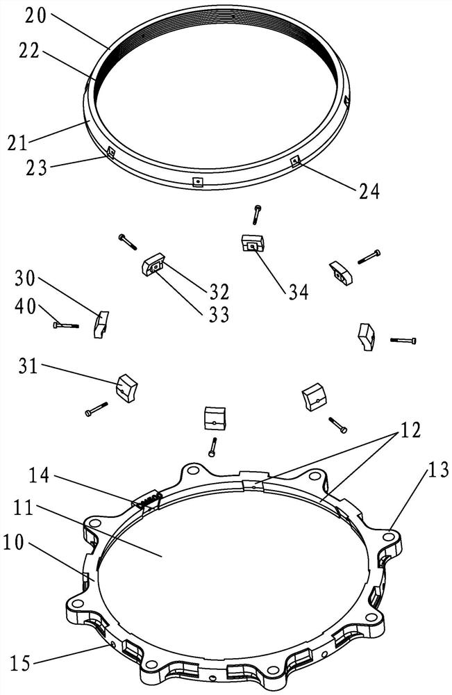
[0060] Such as Figure 1-Figure 2As shown, the present embodiment provides a pipeline anti-disengagement connection assembly, including a gland 10, the gland 10 has a perforation 11, and the inner sidewall of the perforation 11 has a diameter (when its cross section is circular) or a profile diameter (when its cross section is circular) When the cross-section is non-circular), the inclined guide surface 12 gradually decreases from one end to the other end of the through-hole 11 . In this embodiment, the cross-section of the through-hole 11 is circular as an example for illustration. An anti-off ring 20 is arranged in the perforation 11 , and a plurality of adjusting blocks 30 around the axis of the gland 10 are arranged between the anti-off ring 20 and the gland 10 . During use, the pipeline is inserted in the anti-off ring 20 .

[0061] The outer periphery of the gland 10 is provided with a plurality of lugs 13 evenly distributed around the axis of the gland 10, and the lugs...

Embodiment 2

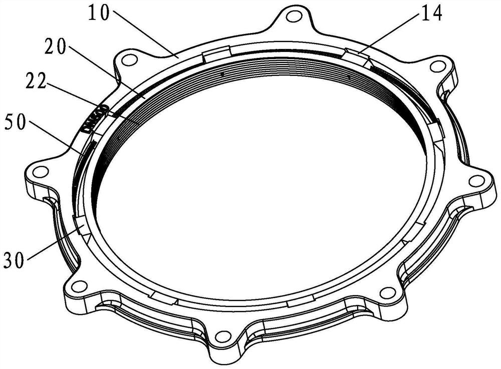
[0069] Such as image 3 shown, and refer to figure 1 and figure 2 As shown, the difference between the anti-disengagement connection assembly provided in this embodiment and the first embodiment is that, in this embodiment, a connecting unit 50 is provided between two adjacent adjustment blocks 30 . The connection unit 50 may be the connection unit used in the fourth embodiment, the fifth embodiment or the sixth embodiment mentioned below, of course, it may be necessary to provide a corresponding matching structure on the adjustment block 30 .

[0070] By setting the connecting unit, each adjusting block 30 can be connected in series in advance to form a ring, so as to avoid loss during use.

Embodiment 3

[0072] Such as Figure 4 shown, and refer to figure 1 and figure 2 As shown, the difference between the anti-off connection assembly provided in this embodiment and the first or second embodiment is that the structure of the anti-off ring 20 is different. Specifically, in this embodiment, the anti-off ring 20 includes a plurality of The adjustment block 30 is arranged in a one-to-one correspondence with the anti-off block 25, and the side of the anti-off block away from the gland 10 has an inclined arrangement from the axial end of the anti-off ring 20 to the other end and gradually away from the gland 10. The inclined push surface 21 and the matching structure of the inclined push surface 21 and the adjusting block 30 are the same as those in the first embodiment, and will not be repeated here.

[0073] This embodiment mainly replaces the ring-shaped ring body in Embodiment 1 or Embodiment 2 with a plurality of anti-off blocks 25, so that when it is necessary to install th...


PUM


Abstract

The invention provides a pipeline anti-disengaging connecting assembly which comprises a gland; the gland is provided with a penetrating hole, the inner side wall of the penetrating hole is provided with an inclined guide face, an anti-disengaging ring is arranged in the penetrating hole, and a plurality of adjusting blocks are arranged between the anti-disengaging ring and the gland; an inclined pushing surface is arranged on the outer side wall of a ring body; or the anti-disengaging ring comprises a plurality of anti-disengaging blocks, and each anti-disengaging block is provided with an inclined pushing surface; and the inclined guide face and an inclined push face incline in the same direction relative to the axis of the gland, the side, facing the gland, of each adjusting block is provided with an outer inclined face, and the side, facing the anti-disengaging ring, of each adjusting block is provided with an inner inclined face. According to the pipeline anti-disengaging connecting assembly, the adjusting blocks are arranged between the anti-disengaging ring and the gland, the pipeline anti-disengaging connecting assembly can be suitable for connection of pipelines with different diameters only by replacing the anti-disengaging ring and the adjusting blocks, the gland can be matched with the pipelines with different diameters, funds and warehouse space needed when the pipeline anti-disengaging connecting assembly is backed up are relatively small, and the pipeline maintenance cost can be reduced favourably.

Description

technical field [0001] The invention relates to a pipeline connector, in particular to a pipeline anti-detachment connection assembly. Background technique [0002] The connection joint of the drainage pipe is usually equipped with a pipeline anti-disengagement connection component. The Chinese utility model patent with the authorized announcement number CN206831008U is a double-layer anti-disconnection joint of the flange designed by the applicant in the early stage. It adopts a combination of a valve cover and an elastic metal pressure ring. Form the anti-disengagement connection assembly of the pipeline to avoid leakage caused by the loosening of the connection joint. However, since the inner diameters of the bonnet and the elastic metal pressure ring are fixed, when the diameters of the drainage pipes are different, different bonnets and elastic metal pressure rings need to be used. However, it is often difficult for the maintenance personnel of the drainage network to k...

Claims


Application Information

Patent Timeline
Patent Type & Authority Applications(China)
IPC IPC(8): F16L21/08
CPCF16L21/08
Inventor 王天琪卢明鑫卢明伟卢志春卢明发
Owner SOUTHEAST PIPE VALVE CO LTD
Why Eureka
Try Eureka