
Patsnap Eureka
For R&D, Patsnap Eureka makes reading and utilizing patents & technical documents easy.
Patsnap Eureka AIR
Designed for self-driven R&D workflows. Generate viable solutions, solve complex R&D challenges, empower your innovation with AI.

Patsnap Eureka Materials
Designed for material experts only. Revolutionize your material R&D, from search, analyze, to developing new materials.

TechResearch
Generate reliable direction feasibility study reports for your R&D in just a few steps.

TechSeek
Discover and master advanced knowledge NOW. Basics, ideas, possibilities, all at once.

TechMind
As an expert in R&D Theories, TechMind can generates customized viable solutions instantly.

TechRisk
Analyze your overall solution with one click, know your potential R&D risks in advance.

TechMonitor
Get weekly tech updates, stay abreast of the latest tech innovations and key insights.
Non-ferrous metal forge piece pulling plate device
A technology for non-ferrous metal and forgings, applied in the field of non-ferrous metal forgings pulling device, can solve the problems of high labor intensity, specification limitation of non-ferrous metal forgings, etc., and achieve the effect of avoiding scratches and scratches
- Summary
- Abstract
- Description
- Claims
- Application Information
AI Technical Summary
Problems solved by technology
Method used
Image

Examples
Embodiment 1
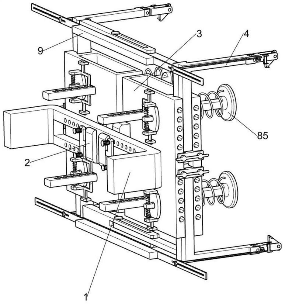
[0039] A non-ferrous metal forging drawing device, such as figure 1 , figure 2 , image 3 , Figure 4 , Figure 5 , Figure 6 , Figure 7 , Figure 8 , Figure 9 , Figure 10 , Figure 11 As shown, it includes an external connector 1, a fixed sliding seat 2, a fixed guide plate 3, a lifting L-shaped plate 4, a width adjustment component 5, a lifting adjustment component 6 and a flipping component 7, and the external connector 1 is slidingly connected with two The fixed sliding seat 2 is fixedly connected with a fixed guide plate 3, and the fixed guide plate 3 is connected with a lifting L-shaped plate 4 in a symmetrical sliding manner. The width adjustment component 5 is located on one side of the fixed sliding seat 2. To adjust the width distance of the lifting L-shaped plate 4, one side of the lifting L-shaped plate 4 is provided with a lifting adjustment assembly 6, which is used to adjust the height distance of the lifting L-shaped plate 4, and is used to support...
Embodiment 2
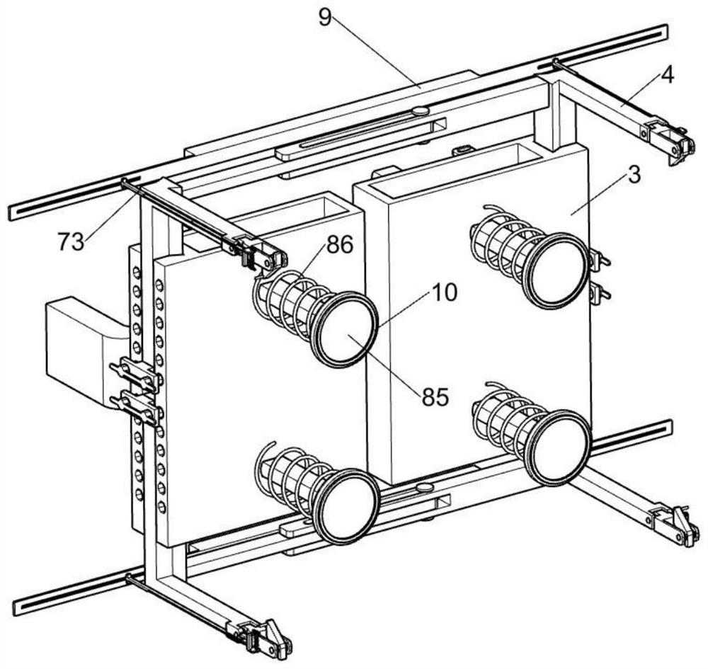
[0047] On the basis of Example 1, such as Figure 11 , Figure 12 As shown, it also includes a forging middle support assembly 8, the fixed guide plate 3 is provided with a forging middle support assembly 8, the forging middle support assembly 8 is used to support the non-ferrous metal forging, the forging middle support assembly 8 includes a current regulator 81, Movable lower pressing rod 82, extruding spring 83, adjusting rod 84, slotted support round seat 85, compression spring 86, fixed electromagnet seat 87, special-shaped clamping rod 88 and tension spring 2 89, one side of movable flip plate 72 is fixedly connected There is a current regulator 81, and the current regulator 81 is used to output current. The current regulator 81 is slidably connected with a movable lower pressure rod 82, and an extruded spring 83 is connected between the movable lower pressure rod 82 and the current regulator 81. An adjustment rod 84 is fixedly connected to the lower pressure rod 82, an...
Embodiment 3
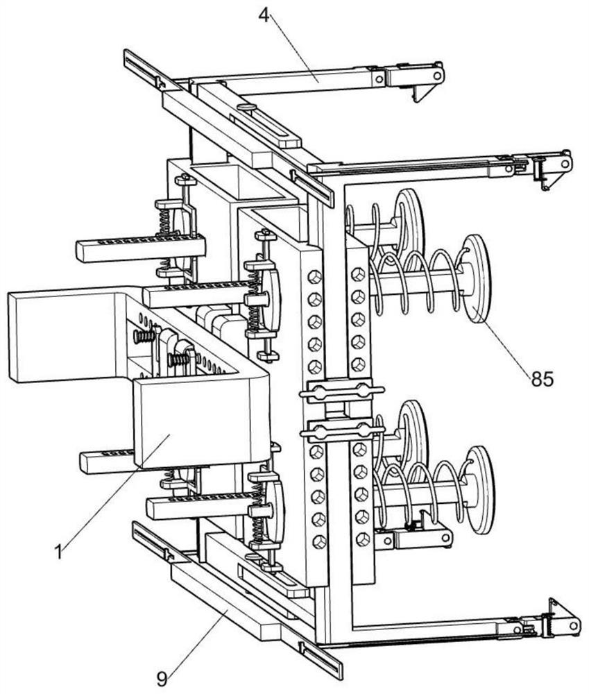
[0050] On the basis of Example 2, such as figure 2 , image 3 As shown, it also includes a connecting pull plate 9, and the two mobile support guide rods 73 at the same level are jointly slidably connected with a connecting pull plate 9, and the connecting pull plate 9 is convenient for the staff to directly pull the two mobile support guide rods 73.
[0051] The staff can directly pull the connection pull plate 9, and the connection pull plate 9 will simultaneously drive the two mobile support guide rods 73 to move away from the non-ferrous metal forging, saving the trouble of the staff pulling the mobile support guide rods 73 one by one.
PUM
 Abstract
Description
Claims
Application Information
 - R&D Engineer
- R&D Manager
- IP Professional
- Industry Leading Data Capabilities
- Powerful AI technology
- Patent DNA Extraction
Browse by: Latest US Patents, China's latest patents, Technical Efficacy Thesaurus, Application Domain, Technology Topic, Popular Technical Reports.
© 2024 PatSnap. All rights reserved.Legal|Privacy policy|Modern Slavery Act Transparency Statement|Sitemap|About US| Contact US: help@patsnap.com