Wind resistance braking device at vehicle end joint of high-speed railway vehicle

A technology for wind resistance braking and high-speed rails, applied in railway braking systems, etc., can solve the problems of destroying the top structure of the car body, small braking force, and reducing the strength of the top, so as to reduce noise pollution, reduce aerodynamic resistance, and ensure reliability. sexual effect

Pending Publication Date: 2022-01-28
SOUTHWEST JIAOTONG UNIV
View PDF9 Cites 2 Cited by
  • Summary
  • Abstract
  • Description
  • Claims
  • Application Information

AI Technical Summary

Problems solved by technology

However, the above research at home and abroad is based on the fact that the brake plate is installed on the top of the car body, so it still has the constraints of destroying the top structure of the car body, reducing the strength of the top, and contributing to aerodynamic drag due to the relatively small area of ​​the brake plate. Power is also relatively small and other issues

Method used


Image

  • Wind resistance braking device at vehicle end joint of high-speed railway vehicle
  • Wind resistance braking device at vehicle end joint of high-speed railway vehicle
  • Wind resistance braking device at vehicle end joint of high-speed railway vehicle

Examples


Embodiment Construction

[0029] The present invention will be further described below in conjunction with the accompanying drawings. It should be noted that this embodiment is based on the technical solution, and provides detailed implementation and specific operation process, but the protection scope of the present invention is not limited to the present invention. Example.

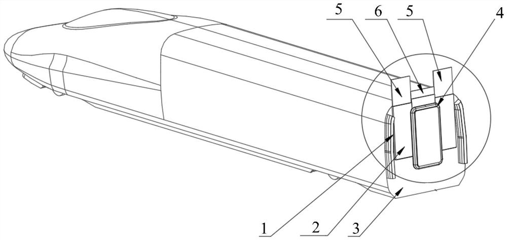
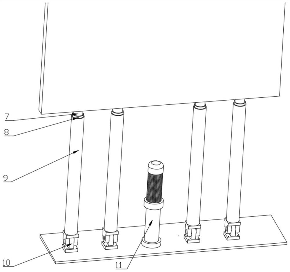
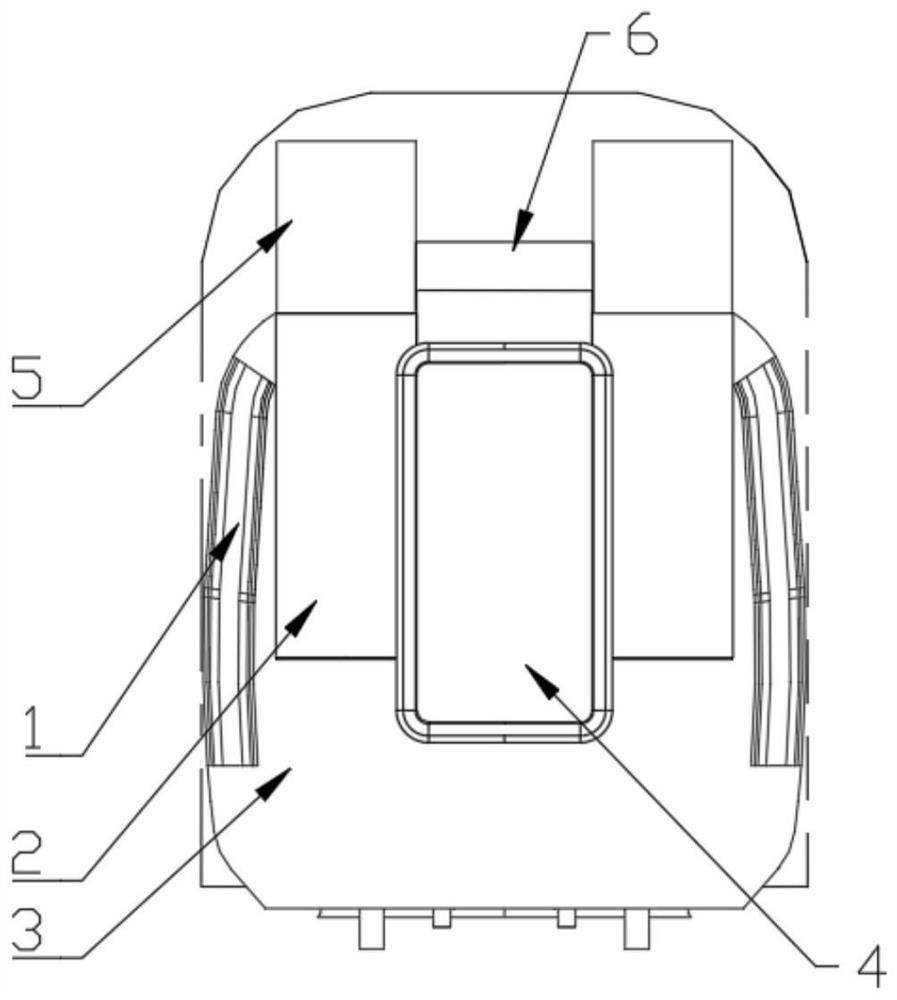
[0030] figure 1 It is a structural schematic diagram of a windage braking device at the car end connection of a high-speed rail vehicle according to an embodiment of the present invention; figure 2 It is a structural diagram of the telescopic unit of the windage braking device at the car end connection of a high-speed rail vehicle according to an embodiment of the present invention; image 3 It is a state diagram when the brake unit of the windage brake device at the car end connection of a high-speed rail vehicle is stretched out according to an embodiment of the present invention; Figure 4 It is a state diagram when the br...


PUM


Abstract

The invention discloses a wind resistance braking device at a vehicle end joint of a high-speed railway vehicle; the device comprises a wind resistance braking mechanism arranged on the end face side of a vehicle, and the wind resistance braking mechanism comprises a braking box fixed to the end face side of the vehicle and a braking unit arranged on the braking box in a penetrating mode through a telescopic unit. When the train runs normally, the braking unit is completely located in the braking box; when the train is braked, the braking unit extends out of the braking box through the telescopic unit. According to the wind resistance braking device for the vehicle end joint of the high-speed railway vehicle, the wind resistance braking mechanism is arranged to be matched with a mechanical braking structure of the train, the braking distance of the train can be effectively shortened, and the braking efficiency of the train is improved; the braking unit is arranged in the braking box located on the end face side of the train, the structural strength of the top end of the train is not damaged, aerodynamic resistance borne by the train during running is reduced, and energy consumption is effectively reduced.

Description

technical field [0001] The invention relates to a wind resistance braking technology, in particular to a wind resistance braking device at the car end connection of a high-speed rail vehicle. Background technique [0002] In recent years, with the in-depth research of high-speed trains by experts at home and abroad, the running speed of trains has been continuously improved. As the train runs faster, the braking performance requirements of the train are higher, especially when the train speed reaches 400km / h or more, the braking distance will increase significantly, and the mechanical braking device alone cannot fully meet the braking requirements. It will also aggravate track wear and endanger the driving safety of high-speed trains. [0003] In order to solve the above problems, wind resistance braking has been developed in recent years. Since the aerodynamic resistance provided by windage braking is proportional to the square of the train speed, making full use of the s...

Claims


Application Information

Patent Timeline
Patent Type & Authority Applications(China)
IPC IPC(8): B61H11/16
CPCB61H11/16
Inventor 李田李一凡戴志远秦登周鹏张继业张卫华
Owner SOUTHWEST JIAOTONG UNIV
Why Eureka
Try Eureka