
Focal plane polarization detection system calibration method

A technology of plane polarization and detection system, which is applied in the direction of measuring the polarization of light, measuring devices, optical radiation measurement, etc. Effect

Pending Publication Date: 2022-01-25
上海济物光电技术有限公司
View PDF0 Cites 1 Cited by
  • Summary
  • Abstract
  • Description
  • Claims
  • Application Information

AI Technical Summary

Problems solved by technology

[0004] Polarization detection cameras can be divided into: time-sharing type, amplitude-dividing type, aperture-dividing type, and focal plane-dividing type. Among them, the focal plane-divided polarization detection camera is the most advanced. It uses an infrared detector equipped with a micro-polarization element structure. time system, the polarization image and polarization angle image can be obtained directly by a single acquisition of the focal plane polarization camera. There will be a large non-uniformity problem

Method used


Image

  • Focal plane polarization detection system calibration method
  • Focal plane polarization detection system calibration method
  • Focal plane polarization detection system calibration method

Examples


Embodiment Construction

[0043]The present invention will be described in detail below in conjunction with specific embodiments. The following examples will help those skilled in the art to further understand the present invention, but do not limit the present invention in any form. It should be noted that those skilled in the art can make several changes and improvements without departing from the concept of the present invention. These all belong to the protection scope of the present invention.

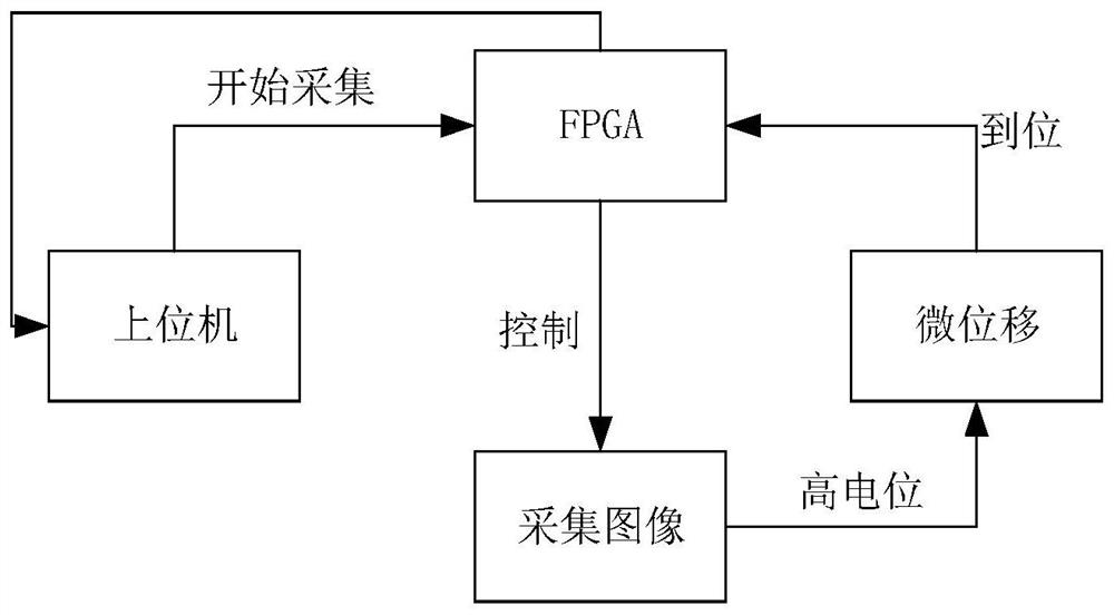
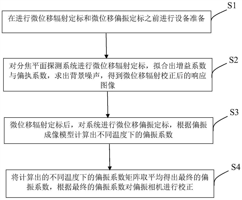
[0044] specifically, figure 1 The schematic block diagram of the image acquisition scheme based on the micro-displacement platform provided for the embodiment of the present invention, wherein the image acquisition scheme based on the micro-displacement platform can be understood as how to use a computer to control the camera to acquire micro-displacement images, figure 2 Shown is a block diagram of the calibration method of the infrared sub-focus plane polarization detection system provided by the embo...


PUM


Abstract

The invention provides an infrared focal plane polarization detection system calibration method. The method comprises the following steps: preparing equipment before micro-displacement radiation calibration and micro-displacement polarization calibration; carrying out micro-displacement radiation calibration on the focal plane detection system, fitting a gain coefficient and a bias coefficient, solving background noise, and obtaining a response image after micro-displacement radiation correction; after micro-displacement radiation calibration, carrying out micro-displacement polarization calibration on the system, and calculating polarization coefficients at different temperatures according to a polarization imaging model; and averaging the calculated polarization coefficient matrixes at different temperatures to obtain a final polarization coefficient, and correcting the polarization camera according to the final polarization coefficient. According to the invention, the spatial noise of the camera can be reduced, and the non-uniformity of the polarization camera can be corrected.

Description

technical field [0001] The invention relates to the technical field of polarization detection, in particular to a calibration method for a focal plane polarization detection system. Background technique [0002] As a useful supplement to intensity detection, polarization detection extends the available information from light intensity, spectrum and space to light intensity, spectrum, space, polarization degree, polarization azimuth, polarization ellipticity and rotation direction, so that more information can be obtained The physical and optical parameters of the medium are of great significance to improve the target detection ability. With the development of optical polarization remote sensing technology, infrared polarization detection has been gradually applied. In order to ensure the measurement accuracy of target infrared polarization radiation characteristics, carry out quantitative research on infrared polarization characteristics of target surface, and better apply p...

Claims


Application Information

Patent Timeline
Patent Type & Authority Applications(China)
IPC IPC(8): G01J4/00
CPCG01J4/00
Inventor 马一哲
Owner 上海济物光电技术有限公司
Learn More