Eureka AIR delivers breakthrough ideas for toughest innovation challenges, trusted by R&D personnel around the world.

Source-sink system quantitative evaluation method

A quantitative evaluation and quantitative model technology, applied in the field of sediment source analysis, which can solve the problems of a large number of drilling seismic data, the inability to quantitatively distinguish the interior of the basin, and the inability to carry out work.

Pending Publication Date: 2022-01-21
CHINA UNIV OF PETROLEUM (EAST CHINA)
View PDF12 Cites 1 Cited by
  • Summary
  • Abstract
  • Description
  • Claims
  • Application Information

AI Technical Summary

Problems solved by technology

[0006] Aiming at the deficiencies in the prior art, the technical problem to be solved by the present invention is to overcome the fact that the existing source-sink system evaluation method requires a large amount of drilling, outcrop and seismic data, cannot work in areas with no or few wells, and cannot quantify In order to distinguish the sediments from different provenances in the basin, a method can be used to quantitatively evaluate the relative contribution of sediments from different parent rock areas in the basin in different time periods in the source-sink system. The source-sink system quantitative evaluation method that can effectively analyze the influence of internal and external dynamic geological processes such as climate change and tectonic activities on the contribution of sediments in different provenance systems during the process from source to sink at any position in the basin

Method used


Image

  • Source-sink system quantitative evaluation method
  • Source-sink system quantitative evaluation method
  • Source-sink system quantitative evaluation method

Examples


Embodiment Construction

[0040] The technical solutions in specific embodiments of the present invention will be described in detail and completely below in conjunction with the accompanying drawings. Apparently, the described embodiments are only some specific implementations of the general technical solution of the present invention, but not all implementations. All other embodiments obtained by those skilled in the art based on the general concept of the present invention fall within the protection scope of the present invention.

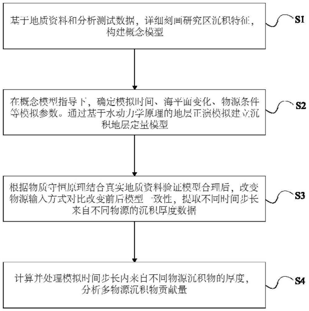
[0041] The present invention provides a source-sink system quantitative evaluation method, comprising the following steps:

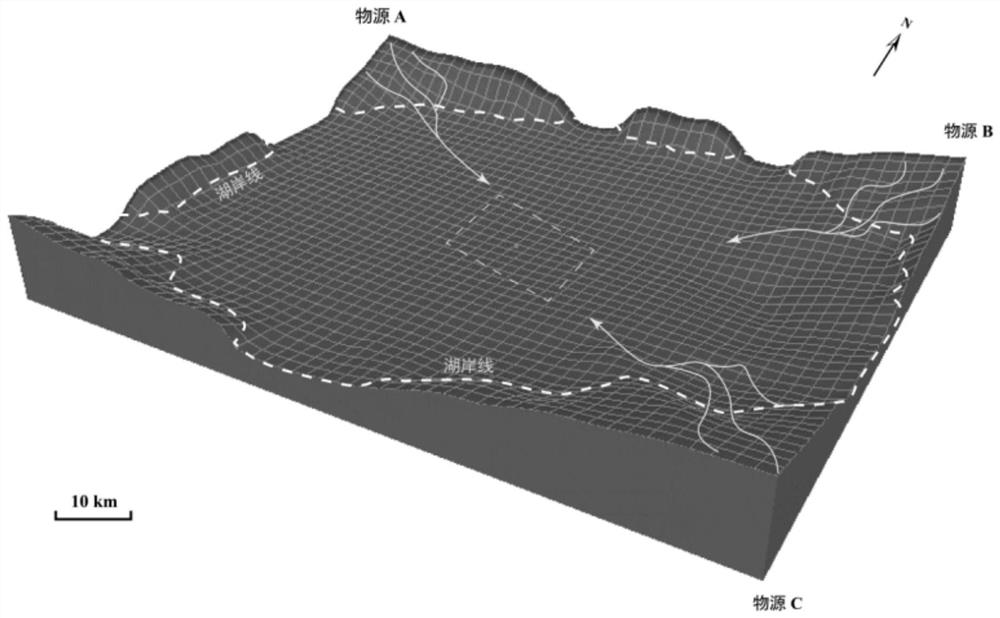
[0042]S1: Construct a conceptual model, including describing the sedimentary characteristics of the study area in detail based on geological data and analytical test data, and constructing a conceptual model. Further, the sedimentary characteristics of the study area were characterized according to field outcrops, core data and drilling seismic da...


PUM


Abstract

The invention discloses a source-sink system quantitative evaluation method, and belongs to the field of sediment source analysis. The method comprises: constructing a conceptual model based on geological data; determining simulation parameters under the guidance of the conceptual model, and establishing a sedimentary stratum quantitative model through stratum forward modeling based on the hydrodynamic principle; based on the principle of conservation of substances, combining with real geological data to verify that the sedimentary model is reasonable, and extracting sedimentary thicknesses from different material sources in different time steps by using the model after the material source input mode is changed; and calculating and processing the thickness of the sediments from different material sources in the simulation time step length, and analyzing the contribution of the sediments from different material sources. The method solves the problems that an existing method cannot carry out work in areas without wells or with few wells, and sediments from different material sources in the basin cannot be quantitatively distinguished. In consideration of internal and external dynamic geological effects such as reference surface lifting and structural activity, the method has the characteristic of quantitatively evaluating the relative contribution of sediments from different mother rock areas in the basin in different time steps in the source-sink system.

Description

technical field [0001] The invention belongs to the technical field of sediment source analysis, and in particular relates to a quantitative evaluation method for a source-sink system. Background technique [0002] The source-sink system is a complete process in which the denudation products formed in the denudation landform area are transported to the sedimentary area or catchment basin and finally deposited. As an interdisciplinary direction, source-sink system research has become the frontier field of Earth system science at home and abroad. This study needs to comprehensively analyze the denudation source area, transport area, final deposition area, and the erosion, dissolution, transport, deposition conversion process, dynamic process, and associated feedback mechanism of sediments as a whole to establish a more accurate Quantitative models of source-sink systems can reveal the dynamic process of the earth system and further guide the exploration and development of eco...

Claims


Application Information

Patent Timeline
IPC IPC(8): G01N33/24G01V1/30
CPCG01N33/24G01V1/306
Inventor 刘可禹高建磊刘建良
Owner CHINA UNIV OF PETROLEUM (EAST CHINA)
Why Eureka
Eureka Blog
Learn More