Paving structure of electric vehicle track in level crossing transition area and construction method of the paving structure

A technology for tram tracks and level crossings. It is applied to the upper structure of the track, the track, and the cohesive pavement paved on site. It can solve the problems of poor road quality, impact load, and dynamic deformation of the road surface, and achieve excellent flexibility and fatigue performance. , prevent water damage and corrosion, the effect of non-slip wheels

Active Publication Date: 2022-01-21
SHANGHAI URBAN CONSTRUCTION MUNICIPAL ENGINEERING (GROUP) CO LTD
View PDF4 Cites 0 Cited by
  • Summary
  • Abstract
  • Description
  • Claims
  • Application Information

AI Technical Summary

Problems solved by technology

However, the laying of tram tracks in the transition zone of existing level crossings is generally that the steel rails are in direct contact with the asphalt pavement, which will cause the following problems: the differential settlement of the steel rails and the road leads to permanent deformation at the joints; Dynamic deformation occurs; there is a difference in settlement at the joint between the rail and the road, resulting in the impact load of social vehicles passing through the intersection, further aggravating the disease, etc.
This will lead to cracking, delamination, slippage, rutting, etc., which will greatly affect the appearance, making the quality of the road surface at the tramway look very poor, and seriously affecting the image of the city

Method used


Image

  • Paving structure of electric vehicle track in level crossing transition area and construction method of the paving structure
  • Paving structure of electric vehicle track in level crossing transition area and construction method of the paving structure
  • Paving structure of electric vehicle track in level crossing transition area and construction method of the paving structure

Examples


Embodiment

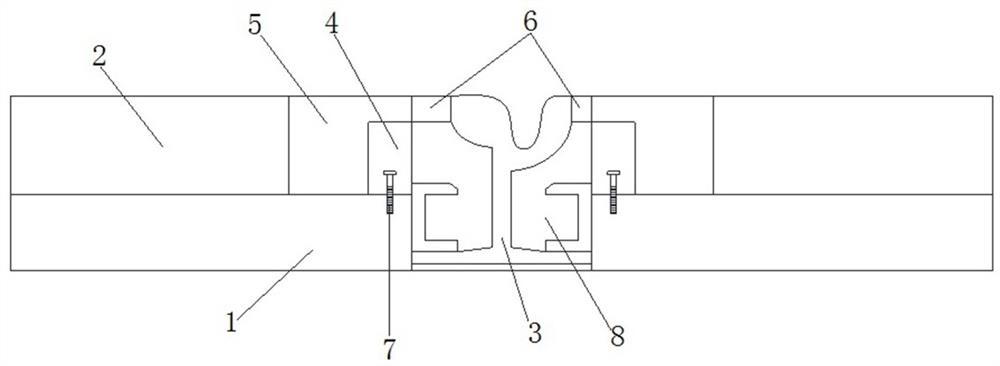
[0035] Example: such as figure 1 As shown, the tram track structure in the level crossing transition area in this embodiment includes a concrete layer 1 as the base layer and an asphalt surface layer 2 as the pavement layer, wherein the asphalt surface layer 2 is laid on the top of the concrete layer 1 . By selecting the high-strength concrete layer 1 as the road base, the strength, stability and durability of the road can be effectively guaranteed, and the asphalt surface layer 2 can be used as the road surface layer to ensure the smoothness of the road surface and improve driving comfort.

[0036] like figure 1 As shown, a through groove is opened at the same position of the concrete layer 1 and the asphalt surface layer 2, that is, the design position of the steel rail, and the through groove penetrates the concrete layer 1 and the asphalt surface layer 2 . A steel rail 3 is installed in the through groove, and both sides of the steel rail 3 have sleepers 8, so that the st...


PUM

PropertyMeasurementUnit
widthaaaaaaaaaa
thicknessaaaaaaaaaa

Abstract

The invention relates to the technical field of road paving, in particular to a paving structure of an electric vehicle track in a level crossing transition area and a construction method of the paving structure. High-elastic self-adaptive asphalt mixture blocks and ultra-high performance concrete blocks are filled between a pavement layer and steel rails; wherein the high-elastic self-adaptive asphalt mixture block and the ultra-high performance concrete block are both arranged above the roadbed layer, and the high-elastic self-adaptive asphalt mixture block is limited between the pavement layer and the ultra-high performance concrete block; and the high-elastic self-adaptive asphalt mixture block and the ultra-high performance concrete block are combined to form a buffer energy absorption transition section of the pavement layer. The structure has the advantages that the problems of cracking, delaminating, slippage, rutting, poor durability and the like can be effectively solved; the structure has high flexibility and self-adaptability, is high in the asphalt consumption; is great in the durability, realizes smooth connection, is high in waterproof performance, and can be repaired together with jointed pavements, is free of maintenance and long in service life, and can rapidly be delivered for traffic, and is simple in maintenance.

Description

technical field [0001] The invention relates to the technical field of road pavement, in particular to a tram track pavement structure and a construction method in a level crossing transition zone. Background technique [0002] Tram has become the best choice for many urban rail transit methods because of its obvious advantages such as low construction cost, low construction difficulty, high safety factor, high environmental protection factor and common use of lanes. However, the laying of tram tracks in the transition zone of existing level crossings is generally that the steel rails are in direct contact with the asphalt pavement, which will cause the following problems: the differential settlement of the steel rails and the road leads to permanent deformation at the joints; Dynamic deformation occurs; there is a difference in settlement at the joint between the rail and the road, resulting in the impact load of social vehicles passing through the intersection, which furth...

Claims


Application Information

Patent Timeline
Patent Type & Authority Applications(China)
IPC IPC(8): E01B21/00E01B19/00E01C9/04E01C9/06E01C3/00E01C7/18
CPCE01B21/00E01B19/003E01C9/04E01C9/06E01C3/00E01C7/18
Inventor 王洪新李晓密宋卿卿姚青江礼高李其秦王琨
Owner SHANGHAI URBAN CONSTRUCTION MUNICIPAL ENGINEERING (GROUP) CO LTD
Why Eureka
Try Eureka