
Film unwinding device

An unwinding device and film technology, which are applied in the fields of film conveying machinery and film conveying and processing, can solve the problems of difficult film rolls to stop rotating and unwinding, unable to meet production and use, and film slack and scattered.

Pending Publication Date: 2022-01-21
浙江耀阳新材料科技有限公司
View PDF0 Cites 0 Cited by
  • Summary
  • Abstract
  • Description
  • Claims
  • Application Information

AI Technical Summary

Problems solved by technology

During the unwinding process of the existing film roll, the film mainly uses the pull of the subsequent process to realize the unwinding and transmission. When the subsequent process breaks down and needs to be temporarily stopped for processing, it is difficult to realize the fast and stable stop of the film roll. The roll will continue to rotate due to the rotational inertia, causing the film to be loose and scattered, causing the film to be skewed and twisted, which affects the accurate and smooth material guide transmission of the film, and it is difficult to achieve efficient and stable unwinding and transmission of the film, which cannot meet the needs of production and use.

Method used


Image

  • Film unwinding device
  • Film unwinding device
  • Film unwinding device

Examples


Embodiment Construction

[0015] In order to further describe the present invention, a specific embodiment of a film unwinding device will be further described below in conjunction with the accompanying drawings. The following examples are explanations of the present invention and the present invention is not limited to the following examples.

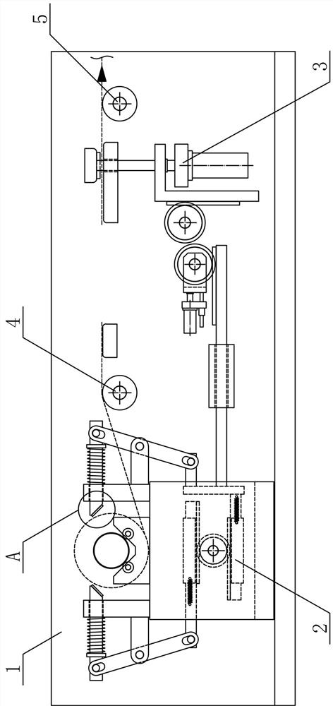
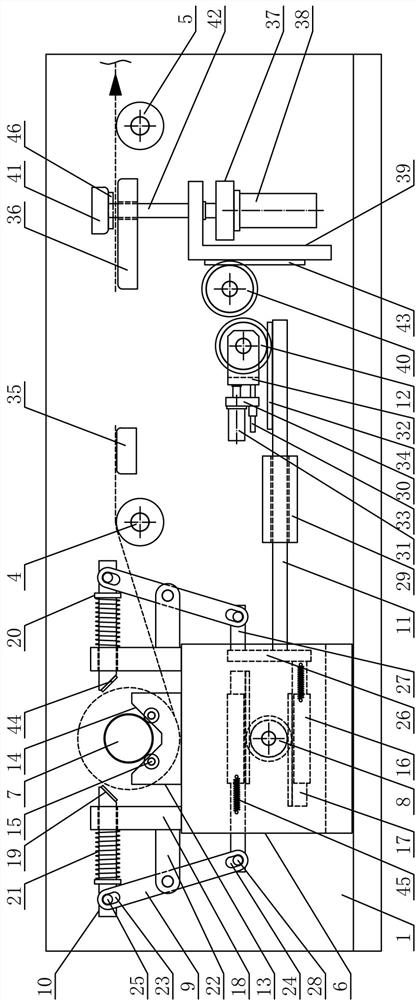
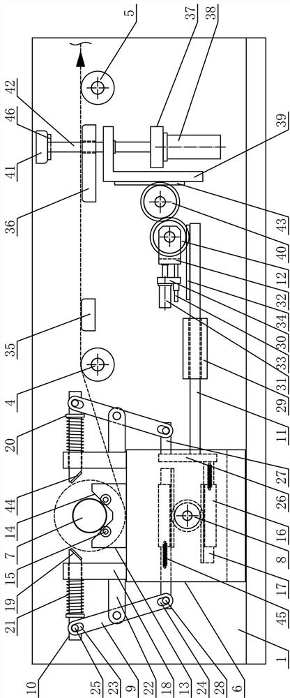
[0016] Such as figure 1 , figure 2 , image 3 , Figure 4 and Figure 5 As shown, a film unwinding device of the present invention includes a film transmission support 1, a film unwinding mechanism 2, a film fixing mechanism 3, a leading film turning roller 4 and a rear leading film turning roller 5, and one side of the film unwinding mechanism 2 The film transmission support 1 is horizontally rotated sequentially along the horizontal direction to connect the leading film turning roller 4 and the rear leading film turning roller 5, and the film pressing mechanism 3 is arranged on the film between the leading film turning roller 4 and the rear leading film t...


PUM


Abstract

The invention discloses a film unwinding device, and belongs to the field of film conveying mechanical equipment. A front film guiding rotating roller and a rear film guiding rotating roller are sequentially, horizontally and rotationally connected to a film conveying support in the horizontal direction, the two ends of a film winding roller are horizontally placed in V-shaped roller placing grooves of unwinding roller bearing plates at the corresponding sides correspondingly, and translation clamping roller rods are horizontally arranged at the two sides of a film unwinding support along the unwinding roller bearing plates at the end of a clamping roller rotating gear correspondingly; and reciprocating rotating connecting plates are symmetrically arranged at the two sides above the clamping roller rotating gear respectively, a clamping roller linkage gear at the output end of a gear horizontal pushing air cylinder is in meshed connection with a pull rod horizontal moving rack at the upper side of a horizontal moving linkage pull rod, the output end of a lifting film pressing air cylinder is fixedly connected with the lower side of a lifting reciprocating connecting plate, and a film pressing lifting plate is horizontally arranged at the upper side of a rear film guiding bearing plate. The film unwinding device is reasonable in structural design, films can be efficiently, stably, accurately and smoothly unwound and conveyed, the film conveying automation degree is improved, and the production and use requirements are met.

Description

technical field [0001] The invention belongs to the field of film conveying machinery and equipment, and in particular relates to a film unwinding device, which is mainly used in the field of film conveying and processing. Background technique [0002] A film is a thin and soft transparent sheet, mainly made of plastic, adhesive, rubber or other materials. The scientific explanation of the film is: a two-dimensional material formed by depositing atoms, molecules or ions on the surface of the substrate. The film Material refers to a thin metal or organic layer with a thickness ranging from a single atom to a few millimeters. Thin films are widely used in electronics, machinery and printing industries, among which electronic semiconductor functional devices and optical coatings are the main applications of thin film technology. According to the classification of raw materials used, film materials can be divided into: polyethylene film, polypropylene film, polyvinyl chloride fi...

Claims


Application Information

Patent Timeline
IPC IPC(8): B65H23/26B65H19/12B65H16/06B65H23/182B65H23/188
CPCB65H23/26B65H19/126B65H16/06B65H23/1825B65H23/1888B65H2701/1133B65H2701/1752
Inventor 陈后良张涛李云锋芦凯
Owner 浙江耀阳新材料科技有限公司
Learn More