


Quick Research
Generate reliable direction feasibility study reports for your R&D in just a few steps.

Technical Q&A
Discover and master advanced knowledge NOW. Basics, ideas, possibilities, all at once.

Find Solutions
As an expert in R&D theories, this can generate solutions to your technical problems instantly.

Evaluate Feasibility
Analyze your overall solution with one click, know your potential R&D risks in advance.

Monitor Landscape
Get weekly tech updates, stay abreast of the latest tech innovations and key insights.
Underwater bionic dolphin machine device and system
A kind of mechanical device and dolphin technology, which is applied to underwater ships, underwater operation equipment, motor vehicles, etc., can solve the problems of being unable to maintain balance, entering the water at a specific angle, and being unable to float and dive, etc., so as to improve the degree of freedom and the effect of flexibility
- Summary
- Abstract
- Description
- Claims
- Application Information
AI Technical Summary
Problems solved by technology
Method used
Image

Examples
Embodiment 1
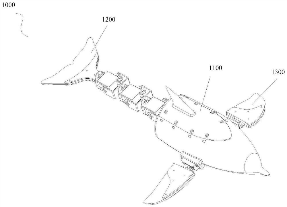
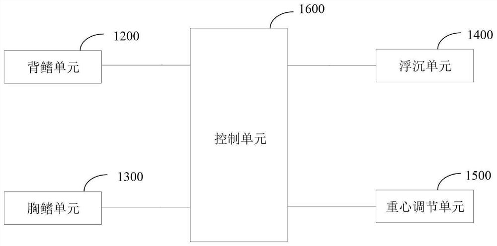
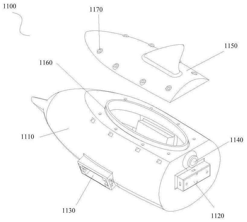
[0138] Such as Figure 1~2 As shown, an underwater bionic dolphin robotic device 1000 includes a main body unit 1100 , a tail fin unit 1200 , a pectoral fin unit 1300 , a floating unit 1400 , a center of gravity adjustment unit 1500 and a control unit 1600 . Wherein, the caudal fin unit 1200 is detachably arranged at the tail end of the main unit 1100, and it at least swings up and down to make the main unit 1100 move forward; the pectoral fin unit 1300 is symmetrically and detachably arranged on both sides of the main unit 1100, and its Rotate at least to make the main unit 1100 change the direction of movement; the floating unit 1400 is arranged inside the main unit 1100 for adjusting the weight of the main unit 1100 so that the main unit 1100 floats or sinks; the center of gravity adjustment unit 1500 is arranged on the main body The interior of the unit 1100 is used to adjust the center of gravity of the main unit 1100 so that the head end of the main unit 1100 remains hor...
Embodiment 2
[0269] This embodiment is a modified embodiment of Embodiment 1. The difference between this embodiment and Embodiment 1 lies in that the structure of the tail fin unit 1200 is different.
[0270] In the first implementation of this embodiment, the tail fin unit 1200 further includes a fourth driving element 1230, and the fourth driving element 1230 is respectively connected to the first driving element 1210, the tail fin element 1220, and is connected to the control unit 1600 for driving the tail fin. Element 1220 rotates.
[0271] Specifically, the fourth driving element 1230 is fixedly connected to the third bracket 1214 of the first driving element 1210 , and the output end of the fourth driving element 1230 is connected to the first connecting bracket 1222 .
[0272] Such as Figure 9a As shown, the fourth driving element 1230 includes a fourth driving motor 1231 , the fourth driving motor 1231 is fixedly connected to the third bracket 1214 , and the output end of the f...
Embodiment approach
[0275] In the second implementation mode of this embodiment, the tail fin unit 1200 further includes a fourth driving element 1230, and the fourth driving element 1230 is respectively connected to the tail end of the main body unit 1100, the first driving element 1210, and is connected to the control unit 1600. The tail fin element 1220 is driven to rotate.
[0276] Specifically, the fourth driving element 1230 is connected to the first installation element 1120 , and the output end of the fourth driving element 1230 is rotatably connected to the first bracket 1211 of the first driving element 1210 .
[0277] Such as Figure 9b As shown, the fourth driving element 1230 includes a fourth driving motor 1231 and a fourth bracket 1232 . Wherein, the output end of the fourth driving motor 1231 is connected to the first connection bracket 1222 ; the fourth bracket 1232 is fixedly connected to the first mounting element 1120 and the fourth driving motor 1231 respectively.
[0278] ...
PUM
 Abstract
Description
Claims
Application Information
 - R&D Engineer
- R&D Manager
- IP Professional
- Industry Leading Data Capabilities
- Powerful AI technology
- Patent DNA Extraction
Browse by: Latest US Patents, China's latest patents, Technical Efficacy Thesaurus, Application Domain, Technology Topic, Popular Technical Reports.
© 2024 PatSnap. All rights reserved.Legal|Privacy policy|Modern Slavery Act Transparency Statement|Sitemap|About US| Contact US: help@patsnap.com