
Welding fixture for profiles, and welding equipment

A technology for welding fixtures and profiles, applied in welding equipment, auxiliary welding equipment, welding/cutting auxiliary equipment, etc., can solve the problem of splicing group equivalence

Pending Publication Date: 2022-01-21
阳江市键恒智能设备有限公司
View PDF0 Cites 0 Cited by
  • Summary
  • Abstract
  • Description
  • Claims
  • Application Information

AI Technical Summary

Problems solved by technology

[0003] The purpose of the present invention is to provide a profile welding fixture, which aims to solve the problem of how to quickly splice and pair two profiles in the prior art

Method used


Image

  • Welding fixture for profiles, and welding equipment
  • Welding fixture for profiles, and welding equipment
  • Welding fixture for profiles, and welding equipment

Examples


Embodiment Construction

[0026] In order to better illustrate the present invention, the present invention will be further described in detail below with reference to the accompanying drawings.

[0027] It should be clear that the described embodiments are only some of the embodiments of the present application, rather than all of the embodiments. Based on the embodiments in the embodiments of the present application, all other embodiments obtained by persons of ordinary skill in the art without making creative efforts belong to the protection scope of the embodiments of the present application.

[0028] The terms used in the embodiments of the present application are only for the purpose of describing specific embodiments, and are not intended to limit the embodiments of the present application. The singular forms "a", "said" and "the" used in the embodiments of this application and the appended claims are also intended to include plural forms unless the context clearly indicates otherwise. It shoul...


PUM


Abstract

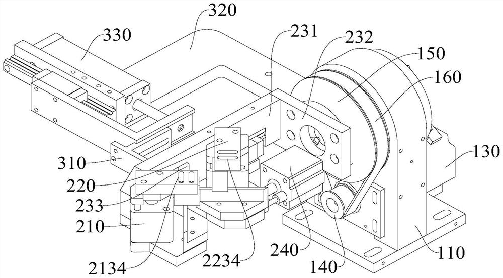
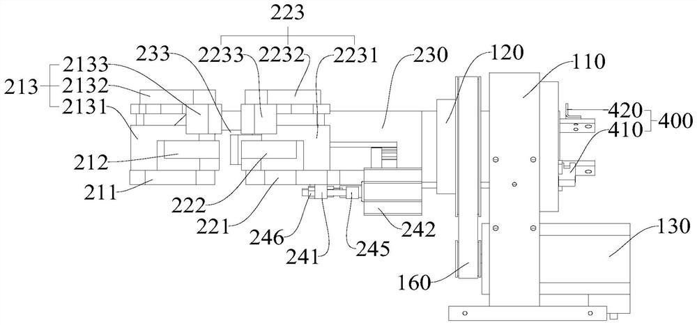
The invention discloses a welding fixture for profiles, and welding equipment. The welding fixture comprises a rotating mechanism, a pressing mechanism and a positioning mechanism, wherein the pressing mechanism is rotationally connected with the rotating mechanism and comprises a first pressing part and a second pressing part; the second pressing part is provided with a positioning position and a butt joint position relative to the first pressing part; the positioning mechanism is fixedly connected with the rotating mechanism and comprises a positioning plate; the positioning plate is arranged between the first pressing part and the second pressing part in a telescopic mode; at the positioning position, the positioning plate extends out, and the first profile on the first pressing part and the second profile on the second pressing part abut against the two opposite side faces of the positioning plate correspondingly; and at the butt joint position, the positioning plate retracts, and the second pressing part moves towards the first pressing part, so that the two profiles are in butt joint. According to the welding fixture for the profiles, and the welding equipment provided by the invention, after the two profiles are positioned and in butt joint through cooperative work of the positioning mechanism and the pressing mechanism, the rotating mechanism drives the pressing mechanism to rotate, and the two profiles are made to rotate, so that all-directional welding work is achieved.

Description

technical field [0001] The invention relates to the technical field of profile welding tooling, in particular to a profile welding fixture and welding equipment. Background technique [0002] In the process of profile processing, according to the actual situation, it is necessary to weld two profiles so that the two profiles form a workpiece with a certain angle. The conventional profile welding process is generally produced by manual welding. In the manual welding process, the welder needs to position and spot weld the two profiles before welding. Moreover, after one side is welded, the two profiles need to be turned over manually. , to weld the other side. There are many processes in the manual welding of profiles, and because the profiles need to be turned manually, welders cannot perform continuous welding work, resulting in adverse consequences of low profile welding efficiency. Contents of the invention [0003] The object of the present invention is to provide a p...

Claims


Application Information

Patent Timeline
Patent Type & Authority Applications(China)
IPC IPC(8): B23K37/04B23K37/047
CPCB23K37/0443B23K37/047
Inventor 高群业赵思记赵世平
Owner 阳江市键恒智能设备有限公司
Learn More