
Gas production rate measuring device of reaction calorimeter

A technology of gas production rate and measuring device, applied in the direction of instruments, analytical materials, etc., can solve the problems of inconvenient measurement process, real-time monitoring, low accuracy of results, etc., and achieve the effect of accurate measurement

Pending Publication Date: 2022-01-18
厦门标安科技有限公司
View PDF0 Cites 0 Cited by
  • Summary
  • Abstract
  • Description
  • Claims
  • Application Information

AI Technical Summary

Problems solved by technology

[0003] While measuring the heat release or heat absorption, it is often necessary to measure the gas produced by the chemical reaction, so as to analyze the chemical reaction process through the gas production and gas production rate. Currently, the U-shaped tube is used to measure the gas produced during the reaction process. The method of gas volume and gas production rate, but it usually needs to be carried out after the reaction calorimetry is over. During the reaction process, the device is in a sealed state, and the air pressure in the device changes greatly, which will easily lead to deviations in the experimental and measurement results; therefore, this method is used The accuracy of the results measured by the method is not high, and the real-time monitoring of the gas production rate cannot be realized. In addition, when the gas production is too much during the reaction process, in order to accommodate more gas, a larger U-shaped tube (measuring device) is required. The measurement process is inconvenient

Method used


Image

  • Gas production rate measuring device of reaction calorimeter
  • Gas production rate measuring device of reaction calorimeter
  • Gas production rate measuring device of reaction calorimeter

Examples


Embodiment Construction

[0019] The present invention will be described in detail below in conjunction with the accompanying drawings and specific embodiments.

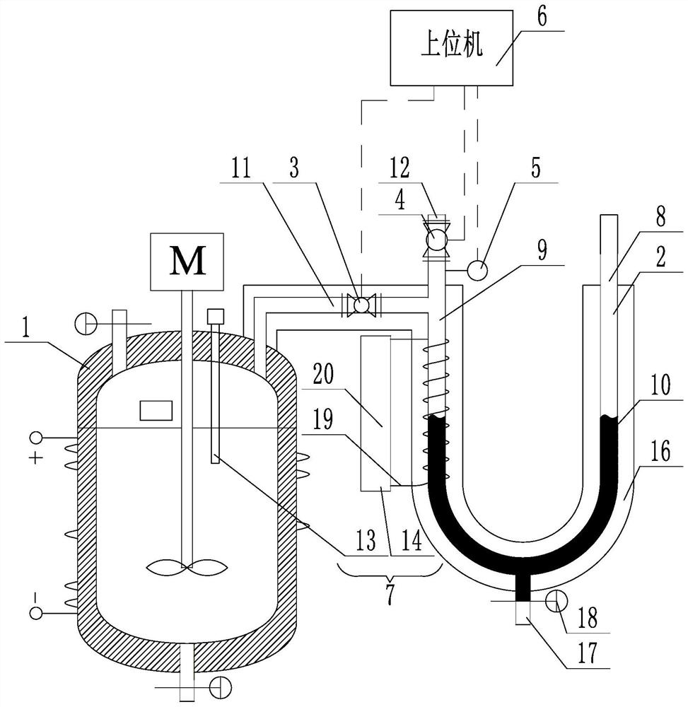
[0020] The invention provides a gas production rate measuring device of a reaction calorimeter, such as figure 1 As shown, it includes a temperature cycle controller 7 installed on the reaction calorimeter 1, a U-shaped pipe 2, a first solenoid valve 3, a second solenoid valve 4, a pressure sensor 5, and a host computer 6. The reaction calorimeter The specific structure of 1 and the principle of measuring the heat of reaction by the reaction calorimeter 1 are all prior art, and will not be elaborated in this embodiment. Preferably, the U-shaped tube 2 is made of glass, and the U-shaped tube 2 is wrapped There is an insulating layer 16, and the insulating layer 16 can be any existing material or structure with heat insulating effect. The U-shaped pipe 2 includes a right branch pipe 8 and a left branch pipe 9 that are connected to each other. ...


PUM


Abstract

The invention discloses a gas production rate measuring device of a reaction calorimeter. The gas production rate measuring device comprises a temperature cycle controller, a U-shaped pipe, a first electromagnetic valve, a second electromagnetic valve, a pressure sensor and an upper computer which are arranged on the reaction calorimeter, wherein the temperature cycle controller comprises a temperature measuring device arranged in the reaction calorimeter and a temperature control device arranged on the U-shaped pipe, the U-shaped pipe comprises a right branch pipe and a left branch pipe which are communicated with each other, indicating liquid is injected into the U-shaped pipe so as to form liquid seal between the right branch pipe and the left branch pipe, the right branch pipe is communicated with the outside, the left branch pipe has a gas inlet and a gas outlet, the gas inlet is communicated with the reaction calorimeter, the gas outlet is communicated with the outside, the first electromagnetic valve is arranged on the gas inlet, the second electromagnetic valve is arranged on the gas outlet, the pressure sensor is arranged in the left branch pipe and connected with the upper computer, and the upper computer is in control connection with the first electromagnetic valve and the second electromagnetic valve. According to the gas production rate measuring device, reaction calorimetry and measurement of reaction produced gas are carried out at the same time, and the limitation that a large measuring device is needed when the produced gas is too much is avoided.

Description

technical field [0001] The invention relates to the technical field of reaction gas production measurement, in particular to a gas production rate measurement device of a reaction calorimeter. Background technique [0002] A reaction calorimeter is a tool used in chemical and pharmaceutical development to measure the heat released or absorbed by a chemical or physical reaction. [0003] While measuring the heat release or heat absorption, it is often necessary to measure the gas produced by the chemical reaction, so as to analyze the chemical reaction process through the gas production and gas production rate. Currently, the U-shaped tube is used to measure the gas produced during the reaction process. The method of gas volume and gas production rate, but it usually needs to be carried out after the reaction calorimetry is over. During the reaction process, the device is in a sealed state, and the air pressure in the device changes greatly, which will easily lead to deviatio...

Claims


Application Information

Patent Timeline
IPC IPC(8): G01N7/16
CPCG01N7/16
Inventor 张鑫林刘阳刘勇军
Owner 厦门标安科技有限公司
Learn More