
Energy recovery and cyclic utilization system for balancing load fluctuation of vibrating screen of combine harvester

A combine harvester and energy recovery technology, which is applied to harvesters, applications, cutters, etc., can solve problems such as energy waste, failure to recover energy, and inability to ensure the cleaning performance of vibrating screens, so as to optimize the working mode and improve the utilization of capacity rate effect

Active Publication Date: 2022-01-18
JIANGSU UNIV
View PDF7 Cites 0 Cited by
  • Summary
  • Abstract
  • Description
  • Claims
  • Application Information

AI Technical Summary

Problems solved by technology

[0004] When the vibrating screen of the grain combine harvester is working, especially under low load conditions, the regular reciprocating swing will generate a lot of energy waste, and cause the body vibration problem of the combine harvester; Insufficient energy reduces screening efficiency
However, most of the vibrating screens of combine harvesters on the market cannot recover their excess energy, nor can they ensure the cleaning performance of the vibrating screens under high loads.

Method used


Image

  • Energy recovery and cyclic utilization system for balancing load fluctuation of vibrating screen of combine harvester
  • Energy recovery and cyclic utilization system for balancing load fluctuation of vibrating screen of combine harvester
  • Energy recovery and cyclic utilization system for balancing load fluctuation of vibrating screen of combine harvester

Examples


Embodiment Construction

[0033] The present invention will be further described below in conjunction with the accompanying drawings and specific embodiments, but the protection scope of the present invention is not limited thereto.

[0034] Embodiments of the present invention are described in detail below, examples of which are shown in the drawings, wherein the same or similar reference numerals designate the same or similar elements or elements having the same or similar functions throughout. The embodiments described below by referring to the figures are exemplary and are intended to explain the present invention and should not be construed as limiting the present invention.

[0035] In describing the present invention, it is to be understood that the terms "central", "longitudinal", "transverse", "length", "width", "thickness", "upper", "lower", "axial", The orientation or positional relationship indicated by "radial", "vertical", "horizontal", "inner", "outer", etc. is based on the orientation o...


PUM


Abstract

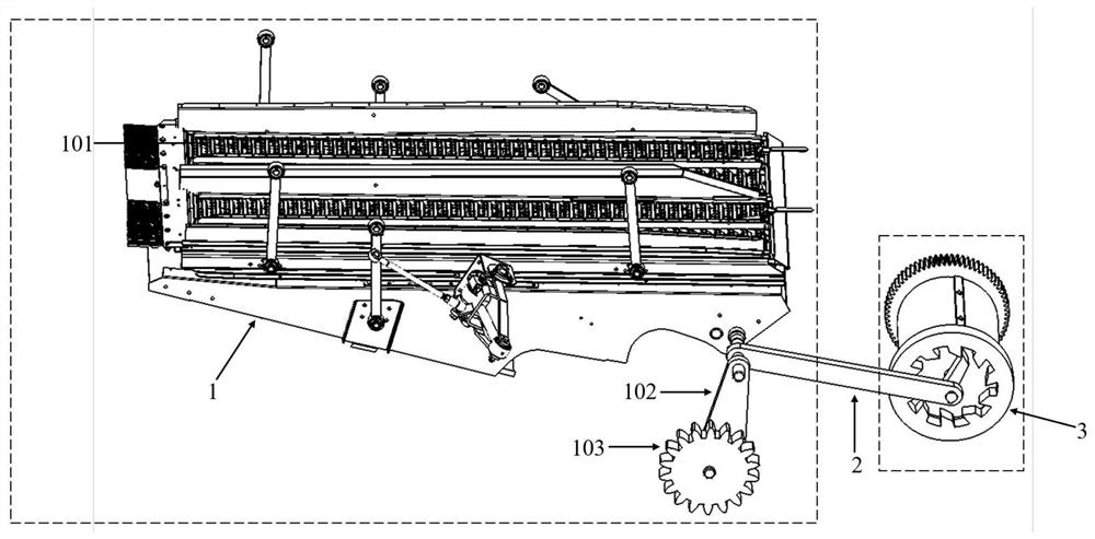
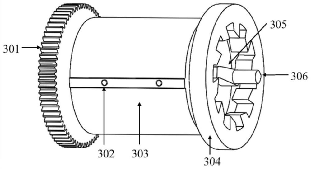
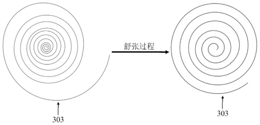
The invention provides an energy recovery and cyclic utilization system for balancing load fluctuation of a vibrating screen of a combine harvester. The energy recovery and cyclic utilization system comprises the vibrating screen, a connecting rod, an energy storage device and a power supply device; one end of the vibrating screen reciprocates through an eccentric device; the eccentric device is connected with the energy storage device through the connecting rod; the energy storage device comprises a transmission gear, a volute spiral spring, a ratchet wheel, a pawl and an energy storage spring shaft; one end of the volute spiral spring is connected with the energy storage spring shaft, and the other end of the volute spiral spring is fixed on a sleeve; the volute spiral spring is connected with the transmission gear, the sleeve is in transmission connection with the connecting rod, the ratchet wheel is arranged at one end of the sleeve, the pawl is installed on the energy storage spring shaft, the pawl is matched with the ratchet wheel, and the ratchet wheel drives the pawl to rotate in a one-way mode; the power supply device comprises a generator and a battery pack; and the transmission gear is in transmission connection with the generator. According to the energy recovery and cyclic utilization system, excess energy generated by the vibrating screen due to load fluctuation can be recovered, and energy cyclic utilization of the vibrating screen under high load can be achieved.

Description

technical field [0001] The invention relates to the field of agricultural machinery, in particular to an energy recovery and recycling system for balancing load fluctuations of a vibrating screen of a combine harvester. Background technique [0002] In recent years, with the introduction of the national strategy of "carbon peaking and carbon neutrality", various industries have paid more attention to fuel pollution and energy recovery. Energy recovery of grain combine harvesters in agricultural machinery has always been a technical problem in the field. The vibrating screen is one of the important components of the grain combine harvester. It separates some impurities and grains from the screen through its own reciprocating swing. However, unlike the rotation in the automotive field, it can directly recycle energy through the generator. However, the reciprocating swing of the vibrating screen of the combine harvester is also a relatively regular movement. At the same time, ...

Claims


Application Information

Patent Timeline
IPC IPC(8): A01D41/12A01D69/06
CPCA01D41/12A01D69/06Y02P60/14
Inventor 唐忠鲁庭钱鹏飞梁亚权章浩
Owner JIANGSU UNIV
Learn More