
Angiography device for cardiovascular disease diagnosis and treatment

A cardiovascular and disease technology, which is applied in the field of imaging devices for the diagnosis and treatment of cardiovascular diseases, and can solve the problems of inconvenient operation, inconvenient disinfection of puncture sites, etc.

Inactive Publication Date: 2022-01-14
杨杰
View PDF1 Cites 1 Cited by
  • Summary
  • Abstract
  • Description
  • Claims
  • Application Information

AI Technical Summary

Problems solved by technology

[0004] A cardiovascular imaging device in the above-mentioned patent has the following disadvantages: before the puncture site is punctured, it is not convenient to quickly disinfect the puncture site, which makes the actual operation process inconvenient

Method used


Image

  • Angiography device for cardiovascular disease diagnosis and treatment
  • Angiography device for cardiovascular disease diagnosis and treatment
  • Angiography device for cardiovascular disease diagnosis and treatment

Examples


Embodiment 1

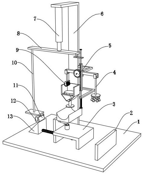
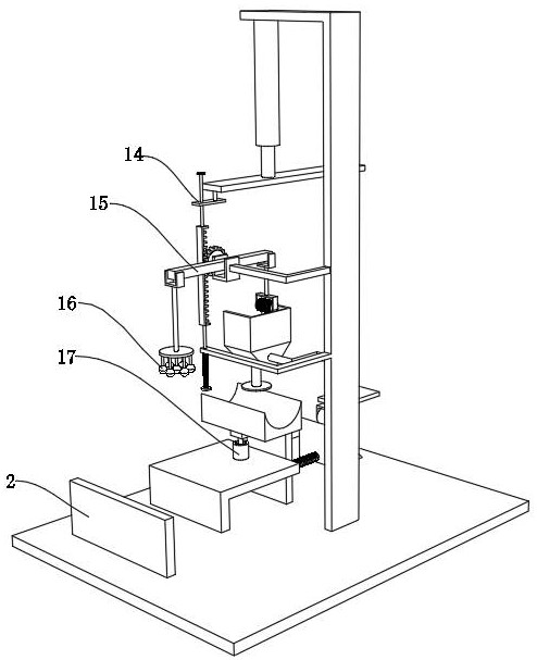
[0035] An imaging device for diagnosis and treatment of cardiovascular diseases, such as Figure 1-6As shown, it includes a base 1, the outer wall of the top of the base 1 is fixed with a support frame 6 by bolts, the outer wall of one side of the support frame 6 is fixed with a lever frame 33 by bolts, and the inner wall of the lever frame 33 is rotatably connected with a gear column 5, The peripheral outer wall of the gear column 5 is fixed with a lever 15 by screws, and the two ends of the lever 15 are connected with a bracket one 32 and a bracket two 38 in rotation respectively, and the bottom outer wall of the bracket two 38 is fixed with a connecting plate 4 by bolts. The outer wall of the bottom of the plate 4 is welded with a massage bar 27, and the outer wall of the massage bar 27 is threadedly connected with a hemostatic ball 16, and the second bracket 38 and the connecting plate 4 can gradually move downward by turning the lever 15, and the second bracket 38 is rotat...

Embodiment 2

[0041] An imaging device for diagnosis and treatment of cardiovascular diseases, such as Figure 1-3 As shown, in order to ensure the safety of puncture; this embodiment makes the following additions on the basis of embodiment 1: the outer wall of the universal ball rod 25 is fixed with an adsorption plate 24 by bolts, and the outer wall of one side of the mounting plate 21 is fixed by bolts. The magnet 22 is fixed, and the adsorption plate 24 can be adsorbed when the puncture is punctured by being provided with the magnet 22, thereby ensuring that the placement seat 23 will not shake during the puncture, thereby ensuring the stability of the puncture. After the puncture is completed, use the horizontal expansion force of the crimping roller 11 to the trapezoidal inclined block 13, so that the adsorption plate 24 can be quickly detached from the magnet 22, so that the hemostatic ball 16 can stop the bleeding at the puncture place, so that the arm Exercise can be done to avoid ...


PUM


Abstract

The invention discloses an angiography device for cardiovascular disease diagnosis and treatment, and relates to the technical field of cardiovascular disease angiography devices. The angiography device aims to facilitate disinfection and hemostasis of a puncture part during angiography; the angiography device comprises a base, and a supporting frame is arranged on the outer wall of the top of the base; a lever frame is arranged on the outer wall of one side of the supporting frame; a gear column is movably connected to the inner wall of the lever frame; a lever is arranged on the outer wall of the circumference of the gear column; the two ends of the lever are movably connected with a first support and a second support respectively; and a connecting plate is arranged on the outer wall of the bottom of the second support. The second support and the connecting plate can gradually move downwards by rotating the lever, the second support is movably connected to one end of a hemostasis ball, and therefore it is guaranteed that the connecting plate is always perpendicular to the horizontal plane in the downward moving process, and the hemostasis ball can press and stop bleeding at the puncture position in the downward moving process; and through the arrangement of an extrusion roller, when the lever rotates reversely, the lever can gradually move to the surface of alcohol cotton.

Description

technical field [0001] The invention relates to the technical field of imaging devices for cardiovascular diseases, in particular to an imaging device for diagnosis and treatment of cardiovascular diseases. Background technique [0002] Cardiovascular angiography is to quickly inject a contrast agent containing organic compounds into the blood stream that is transparent under X-ray irradiation, so that the heart and large blood vessel cavity can be visualized under X-ray irradiation. During cardiovascular angiography, it is generally necessary to percutaneously puncture the femoral artery and vein into the cardiac catheter. Before the puncture, the puncture site needs to be disinfected. After the puncture, the puncture site needs to be pressed to stop bleeding. However, the current existing devices It is impossible to take both into account at the same time, so that there is a lot of inconvenience in actual operation. [0003] After searching, the Chinese patent application...

Claims


Application Information

Patent Timeline
Patent Type & Authority Applications(China)
IPC IPC(8): A61B17/12A61M35/00
CPCA61B17/12A61M35/20A61B2017/12004
Inventor 杨杰刘芸
Owner 杨杰
Learn More