
Lifting mechanism for lifting mop and cleaning machine

A lifting mechanism and mop technology, which is applied in the field of cleaning machines, can solve problems such as center of gravity changes, heavy overall weight, and unfavorable stable operation of cleaning machines, and achieve reliable lifting functions and improved reliability

Pending Publication Date: 2022-01-14
NINGBO FUJIA IND
View PDF0 Cites 2 Cited by
  • Summary
  • Abstract
  • Description
  • Claims
  • Application Information

AI Technical Summary

Problems solved by technology

[0002] There is a cleaning machine that has important market value because it can automatically rotate and mop the floor. However, each rotating mop unit in the current cleaning machine is usually lifted as a whole, that is, it drives the frame on which each mop unit is installed. Or the overall lifting of the housing, each drive mechanism needs to be installed on the frame or the housing, and the driving mechanism is used to drive the mop unit to rotate and clean, that is to say, the mop unit is indirectly lifted and lowered, which leads to a heavier overall weight. The applicant found that the overall lift The technical route makes the center of gravity easy to change, which has a negative impact on the stable operation of the cleaning machine. Therefore, in the process of design, production, and manufacturing, special attention must be paid to the matching of the center of gravity under different circumstances of lifting. Not only the structure is complicated, but also the design, production , manufacturing are more cumbersome, the cost is relatively high

Method used


Image

  • Lifting mechanism for lifting mop and cleaning machine
  • Lifting mechanism for lifting mop and cleaning machine
  • Lifting mechanism for lifting mop and cleaning machine

Examples


Embodiment Construction

[0030] The following description serves to disclose the present invention to enable those skilled in the art to carry out the present invention. The preferred embodiments described below are only examples, and those skilled in the art can devise other obvious variations. The basic principles of the present invention defined in the following description can be applied to other embodiments, variations, improvements, equivalents and other technical solutions without departing from the spirit and scope of the present invention.

[0031] Those skilled in the art should understand that in the disclosure of the present invention, the terms "vertical", "transverse", "upper", "lower", "front", "rear", "left", "right", " The orientation or positional relationship indicated by "vertical", "horizontal", "top", "bottom", "inner", "outer", etc. is based on the orientation or positional relationship shown in the drawings, which are only for the convenience of describing the present invention...


PUM


Abstract

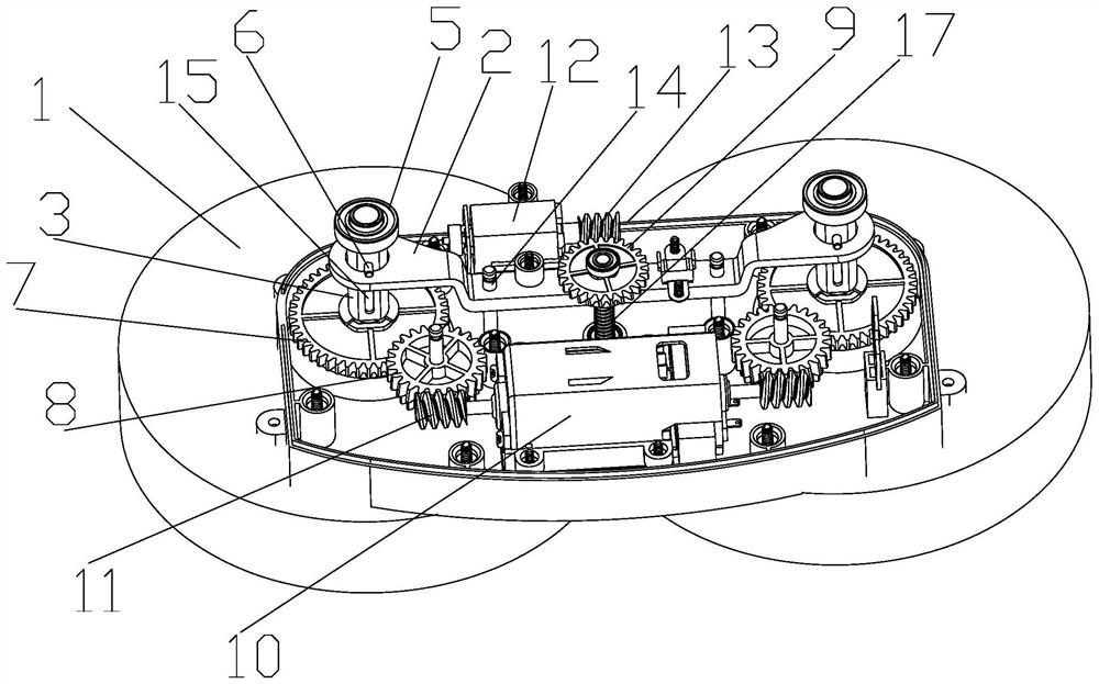
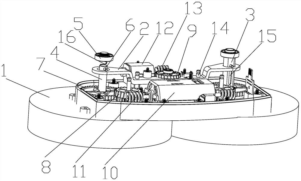
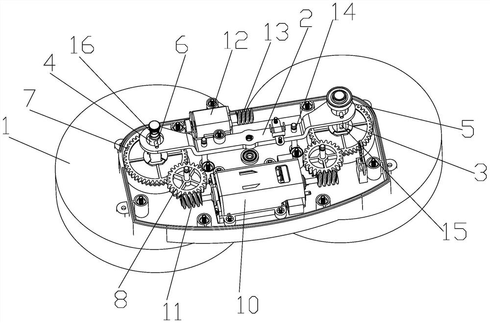
The invention discloses a lifting mechanism for a lifting mop, the lifting mechanism comprises a driving unit and further comprises a lifting part capable of moving up and down, the lifting part is connected with a rotating shaft of a mop unit, the lifting part is used for driving the rotating shaft to move axially, a driving part of the driving unit is used for lifting the lifting part, and direct lifting of the mop is facilitated, the problem that the lifting part is heavy is solved; the invention further provides a cleaning machine which adopts the lifting mechanism for lifting the mop.

Description

technical field [0001] The invention relates to the technical field of cleaning equipment, in particular to a lifting mechanism for lifting a mop and a cleaning machine. Background technique [0002] There is a cleaning machine that has important market value because it can automatically rotate and mop the floor. However, each rotating mop unit in the current cleaning machine is usually lifted as a whole, that is, it drives the frame on which each mop unit is installed. Or the overall lifting of the housing, each drive mechanism needs to be installed on the frame or the housing, and the driving mechanism is used to drive the mop unit to rotate and clean, that is to say, the mop unit is indirectly lifted and lowered, which leads to a heavier overall weight. The applicant found that the overall lift The technical route makes the center of gravity easy to change, which has a negative impact on the stable operation of the cleaning machine. Therefore, in the process of design, pr...

Claims


Application Information

Patent Timeline
Patent Type & Authority Applications(China)
IPC IPC(8): A47L11/283A47L11/40
CPCA47L11/283A47L11/4002A47L11/4038A47L11/4058A47L11/4069A47L11/4055A47L11/4063A47L11/282A47L11/4011
Inventor 方剑强汪旭
Owner NINGBO FUJIA IND
Learn More