
Power control circuit based on E-type power amplifier

A power amplifier and power control technology, applied in the direction of amplification control, gain control, electrical components, etc., can solve problems such as increasing the complexity of circuit design, improve the adjustment range and adjustment flexibility, simplify circuit design, and enhance non-ideal The effect of the characteristic

Pending Publication Date: 2022-01-11
HUAZHONG UNIV OF SCI & TECH
View PDF0 Cites 0 Cited by
  • Summary
  • Abstract
  • Description
  • Claims
  • Application Information

AI Technical Summary

Problems solved by technology

Traditional measures to increase the output power adjustment range of Class E power amplifiers have greatly increased the complexity of circuit design, which is contrary to its original intention of low-cost application scenarios

Method used


Image

  • Power control circuit based on E-type power amplifier
  • Power control circuit based on E-type power amplifier
  • Power control circuit based on E-type power amplifier

Examples


Embodiment Construction

[0026] In order to make the object, technical solution and advantages of the present invention clearer, the present invention will be further described in detail below in conjunction with the accompanying drawings and embodiments. It should be understood that the specific embodiments described here are only used to explain the present invention, not to limit the present invention. In addition, the technical features involved in the various embodiments of the present invention described below can be combined with each other as long as they do not constitute a conflict with each other.

[0027] In the present invention, the terms "first", "second" and the like (if any) in the present invention and drawings are used to distinguish similar objects, and are not necessarily used to describe a specific order or sequence.

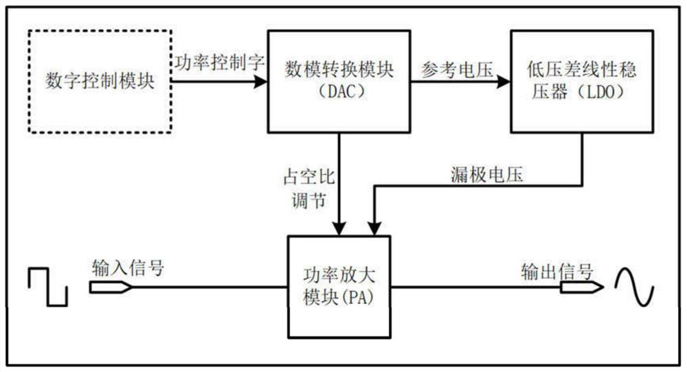
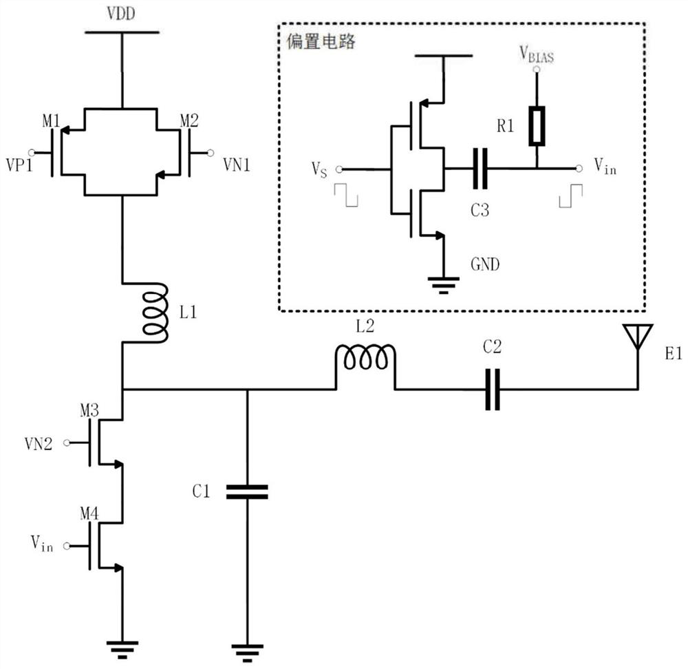
[0028] figure 1 A structural block diagram of a power control circuit based on a class-E power amplifier provided by an embodiment of the present invention. refe...


PUM


Abstract

The invention discloses a power control circuit based on an E-type power amplifier, and belongs to the field of radio frequency integrated circuits. The circuit comprises a digital control module for generating and outputting digital control bits corresponding to a target power value; a digital-to-analog conversion module, wherein the input of the digital-to-analog conversion module is connected with the output of the digital control module, and the digital control bits are converted into corresponding direct-current bias voltage which is output through a first output port; a power amplification module, wherein the input side of the power amplification module is provided with a bias circuit, a bias node of the bias circuit is connected with the first output port, an external square wave signal is input into the power amplification module under the action of the bias circuit, and the square wave signal is a non-ideal square wave signal; the DC bias voltage changes the DC bias of the square wave signal so as to adjust the duty ratio of the signal actually input to the power amplification module, thereby adjusting the output power of the power amplification module. The non-ideal characteristic of a square wave signal transmitted in an actual circuit is utilized, the duty ratio adjustment is realized by controlling the direct current bias of an input signal, and the circuit design complexity is simplified.

Description

technical field [0001] The invention belongs to the field of radio frequency integrated circuits, and more specifically relates to a power control circuit based on a class E power amplifier. Background technique [0002] In traditional Class A, B, and C power amplifiers (Power Amplifier, PA), transistors are used as controlled current sources, working in the saturation region, and linearly amplifying input signals, which can be applied to all modulation methods. However, the inherent DC bias current of the transistor will cause a large energy loss, so the efficiency of the traditional linear amplifier is low. In the non-linear class E power amplifier, the input switching tube works in the cut-off area and the linear area, the digital frequency modulation signal controls the periodic conduction and disconnection of the input MOS tube, and the amplified voltage and current signal is output, and then obtained through the frequency selection network. The input signal is a sine ...

Claims


Application Information

Patent Timeline
IPC IPC(8): H03G3/30
CPCH03G3/3042
Inventor 刘冬生单晓煜金子睿胡昂刘子龙张成成
Owner HUAZHONG UNIV OF SCI & TECH
Learn More