
Energy-saving type mine cable rapid suspension equipment

A mine cable and suspension equipment technology, applied in mining equipment, mining equipment, electrical components, etc., can solve problems such as suspension troubles, looseness, and cable sagging, and achieve the effects of convenient operation, sliding action, and safe distance distance

Active Publication Date: 2022-01-11
ANHUI CABLE
View PDF4 Cites 0 Cited by
  • Summary
  • Abstract
  • Description
  • Claims
  • Application Information

AI Technical Summary

Problems solved by technology

[0005]Aiming at the deficiencies of the prior art, the present invention provides an energy-saving type of quick suspension equipment for mine cables, which solves the problem that most of the suspension structures in the prior art are single It is more troublesome to hang, and the hanging parts will often fall or loosen during the hanging, which will cause the cable to hang down, which will affect the unnecessary re-hanging operation

Method used


Image

  • Energy-saving type mine cable rapid suspension equipment
  • Energy-saving type mine cable rapid suspension equipment
  • Energy-saving type mine cable rapid suspension equipment

Examples


Embodiment 1

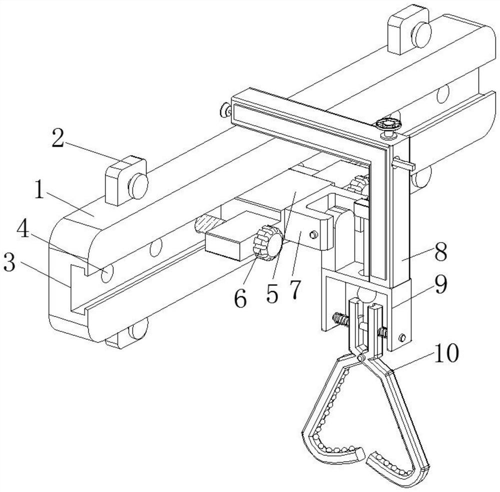
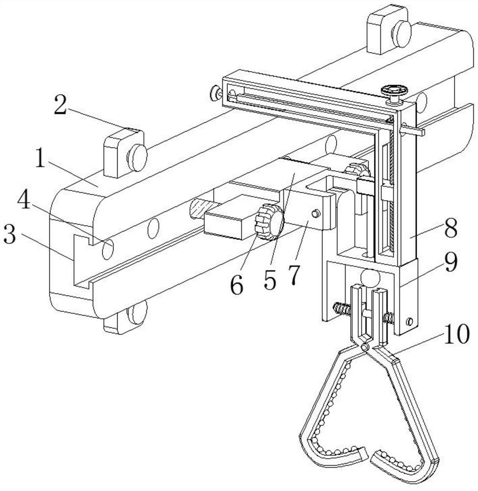
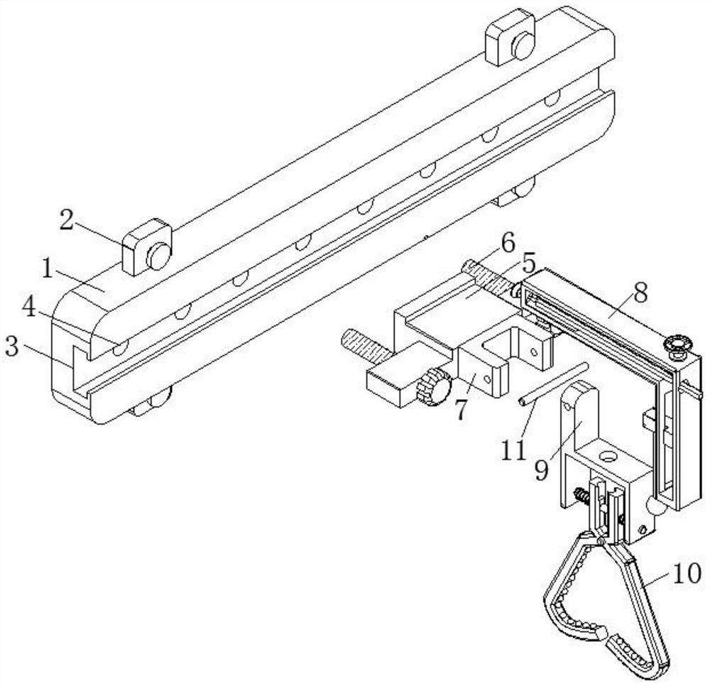
[0034] Such as Figure 1-6 As shown, the present invention provides a technical solution: an energy-saving quick suspension equipment for mine cables, including a mounting part, the mounting part is a rectangular mounting seat 1, and the right side wall of the rectangular mounting seat 1 is provided with a length equal to that of the rectangular mounting seat 1. Consistent T-shaped slot 3, T-shaped slider 5 slides inside the T-shaped slot 3, and the end of T-shaped slider 5 away from T-shaped slot 3 is fixed with a rotating seat 7, which is in the shape of "匚" and rotates A rotating shaft 11 is installed between the inner walls of the seat 7, and the outer circular surface of the rotating shaft 11 is movably connected with an adjusting assembly 9, so as to ensure that the adjusting assembly 9 can be perpendicular to the horizontal ground;

[0035] Specifically, the adjustment assembly 9 includes a fixed seat 901 that is movably connected to the outer surface of the rotating sh...

Embodiment 2

[0042] Such as Figure 7 As shown, this embodiment is basically the same as Embodiment 1. Preferably, the mounting part is also a U-shaped mounting seat 12, and the T-shaped groove 3 is also "U-shaped" and surrounded on the front surface of the U-shaped mounting seat 12.

[0043] Specifically, the use of the U-shaped mounting base 12 in conjunction with the T-shaped groove 3 can enable the advancing assembly 8, the adjusting assembly 9, and the clamping assembly 10 to move on a curved surface, and the use of multiple U-shaped mounting bases 12 can make The cable is bent and suspended on the wall of the tube well, which saves the space for cable suspension and further improves the practicability of the device.


PUM


Abstract

The invention relates to the technical field of cable suspension, and discloses energy-saving type mine cable rapid suspension equipment. The equipment comprises a mounting part, the mounting part is a rectangular mounting base, a T-shaped groove consistent with the rectangular mounting base in length is formed in the right side wall of the rectangular mounting base, and a T-shaped sliding block slides in the T-shaped groove; and a rotating base is fixed to the end, away from the T-shaped groove, of the T-shaped sliding block and is in a U shape, a rotating shaft is rotationally installed between the inner side walls of the rotating base, and the outer circle face of the rotating shaft is movably connected with an adjusting assembly so that it can be guaranteed that the adjusting assembly can be perpendicular to the horizontal ground. The problems that in the prior art, most suspension structures are single, suspension is troublesome, and unnecessary secondary suspension operation is affected due to the fact that a suspension part falls off or loosens during suspension and consequently a cable falls off are solved.

Description

technical field [0001] The invention relates to the technical field of cable suspension, in particular to an energy-saving quick suspension equipment for mine cables. Background technique [0002] As a special cable in the mining industry, the mine cable has the characteristics of large unit length and mass, and the mine cable needs to be suspended to ensure the stable operation of the cable during mine operations. Generally, the mine cable is suspended by hanging the cable on its pipe wall In addition, it can not only effectively save the pipeline space, but also increase its aesthetics. [0003] Most of the existing mine cable suspension equipment has a simple suspension structure, which is cumbersome to hang, and the hanging parts often fall or become loose during the suspension, causing the cable to sag, which affects unnecessary re-suspension operations. Contents of the invention [0004] (1) Solved technical problems [0005] Aiming at the deficiencies of the prior...

Claims


Application Information

Patent Timeline
IPC IPC(8): H02G3/02E21F17/02E21F17/06
CPCH02G3/02E21F17/02E21F17/06
Inventor 徐晓丽周俊朱道进朱元忠陈安鹏郑斌陶恒莹高美玲夏候东杨春红崇时凤
Owner ANHUI CABLE
Learn More