Convenient-to-position circuit breaker and mounting method thereof

A circuit breaker and circuit breaker body technology, which is applied to circuits, emergency protection devices, and parts of protective switches. It can solve problems such as inability to generalize, messy wiring harnesses, and inconvenient space for circuit breakers, and achieve convenient installation and good installation effects. Effect

Active Publication Date: 2021-02-23
常州中联飞机制造有限公司 +1
View PDF2 Cites 0 Cited by
  • Summary
  • Abstract
  • Description
  • Claims
  • Application Information

AI Technical Summary

Problems solved by technology

[0004] 1. The connected wiring harness is messy and cannot be summarized, which is inconvenient for maintenance;
[0005] 2. There is no mutual fixation between two adjacent circuit breakers, and the fixation form is relatively simple;
[0006] 3. When the circuit breaker is fixed on the guide rail, because the length of the guide rail is different, the circuit breaker as a whole is not convenient to completely occupy the overall space, resulting in a waste of space

Method used


Image

  • Convenient-to-position circuit breaker and mounting method thereof
  • Convenient-to-position circuit breaker and mounting method thereof
  • Convenient-to-position circuit breaker and mounting method thereof

Examples


Embodiment 1

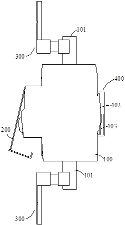
[0059] Such as Figure 1~11 As shown, the present invention provides a circuit breaker for easy positioning, including a circuit breaker body 100 and a sliding plate 400. The back of the circuit breaker body 100 has a card sliding plate, and the card sliding plate includes a Two slide grooves 103 and an inverted tip platform 102 arranged in parallel at the back of the

[0060] The sliding plate 400 is provided with a beveled groove 401 adapted to the beveled platform 102 , and sliding edges 402 adapted to the chute 103 are arranged in parallel on the upper and lower end surfaces of the beveled groove 401 .

[0061] The positioning and fixing of the circuit breaker body 100 on the sliding plate 400 is realized through the cooperation of the circuit breaker body 100 with the sliding plate 400; the inverted tip platform 102 is clamped in the inverted tip groove 401 and forms the effect of fitting and fixing the inclined surface to achieve good support Effect: through the sliding...

Embodiment 2

[0083] Embodiment two is carried out on the basis of embodiment one.

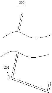
[0084] The circuit breaker includes a circuit breaker body 100 with a cover 200 and a positioning part 300; two vertical pipes 101 respectively extend from the two wiring ports of the circuit breaker body 100, and each of the vertical pipes 101 is provided with at least one positioning part. Part 300;

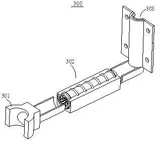
[0085] There is a piercing opening on the side wall of the vertical pipe 101 , and a long rib 201 is provided at the back bend of the cover 200 ; the positioning part 300 includes a The holding half ring 301 on the top, the telescopic tube 302 fixedly connected with the holding half ring 301 and the vertical shelf plate 303 arranged on the upper end surface of the telescopic tube 302, the vertical shelf plate 303 includes a cross section of The semicircular wire conduit 3031 and the positioning plate 3032 integrally arranged on both sides of the wire conduit 3031, the wire outlet of the telescopic tube 302 ...


PUM


Abstract

The invention relates to a circuit breaker convenient to position and a mounting method thereof. The circuit breaker comprises a circuit breaker body and a sliding plate. The back of the circuit breaker body is provided with a clamping sliding plate, and the clamping sliding plate comprises two sliding grooves which are close to the back of the circuit breaker body and are arranged in parallel andan inverted sharp table. An inverted sharp groove matched with the inverted sharp table is formed in the sliding plate, and sliding edges matched with the sliding grooves are arranged on the upper end face and the lower end face of the inverted sharp groove in parallel. The circuit breaker body is matched with the sliding plate, so that the circuit breaker body is positioned and fixed on the sliding plate; the inverted sharp table is clamped in the inverted sharp groove to form an inclined surface fitting and fixing effect, so that a good supporting effect is achieved; and the sliding edges are matched with the sliding grooves, so that an overall sliding effect is achieved.

Description

technical field [0001] The invention relates to a circuit breaker, in particular to a conveniently positioned circuit breaker and an installation method thereof. Background technique [0002] The circuit breakers in the prior art are usually arranged in a single row, and when arranged, they are mainly hung on a guide rail, and then two circuit breakers arranged side by side are fixed to each other to achieve the effect of erection. [0003] Among them, this type of circuit breaker positioning has the following disadvantages: [0004] 1. The connected wiring harness is messy and cannot be summarized, which is inconvenient for maintenance; [0005] 2. There is no mutual fixation between two adjacent circuit breakers, and the fixation form is relatively simple; [0006] 3. When the circuit breaker is fixed on the guide rail, because the length of the guide rail is different, it is not convenient for the circuit breaker as a whole to completely occupy the overall space, result...

Claims


Application Information

Patent Timeline
IPC IPC(8): H01H71/02H01H71/10
CPCH01H71/02H01H71/10
Inventor 戴文伟吴方庆
Owner 常州中联飞机制造有限公司
Why Eureka
Try Eureka