Movable operation cabin structure

A mobile operation and operation cabin technology, applied in the field of rail transit, can solve the problems of potential safety hazards, only one operation cabin, and limited field of vision, and achieve the effects of ensuring safety, reducing work risks, and improving work efficiency

Pending Publication Date: 2022-01-11
一路行(北京)科技有限公司
View PDF0 Cites 0 Cited by
  • Summary
  • Abstract
  • Description
  • Claims
  • Application Information

AI Technical Summary

Problems solved by technology

[0006] The purpose of the present invention is to provide a mobile operating cabin structure to solve the technical problem that there is only one operating cabin for mechanical equipment in the prior art, and the field of vision on one side is limited during the operation process, and there is a technical problem of potential safety hazards; the present invention provides The many technical effects that can be produced by the preferred technical solutions among the many technical solutions are detailed in the following descriptions

Method used


Image

  • Movable operation cabin structure
  • Movable operation cabin structure
  • Movable operation cabin structure

Examples


Embodiment 1

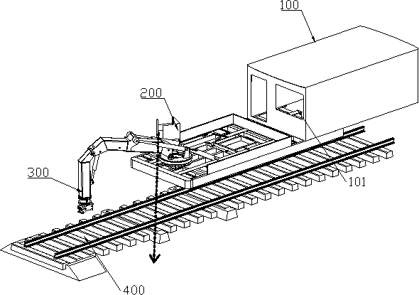
[0048] Such as Figure 3-Figure 9 As shown, the mobile operating cabin structure of this embodiment includes a base 1 located on the operating vehicle body, a supporting rotation mechanism and an operating cabin 10, wherein: the base 1 is provided with operating components, wherein the operating components can be mechanical arms 300 Components used for construction operations, etc., are described below using the mechanical arm 300 as an example. The peripheral wall of the base is provided with a guide rail 2; the operation cabin 10 is fixed on the support rotation mechanism, and the support rotation mechanism is movable along the guide rail 2, and the operation cabin 10 can be driven by the support rotation mechanism along the guide rail 2 by a mechanical arm. Rotate to the other opposite side of the arm and lock with base 1.

[0049] Wherein, the above-mentioned base 1 is the same as in the prior art, and it can be rotatably arranged on the work vehicle body to drive the mec...

Embodiment 2

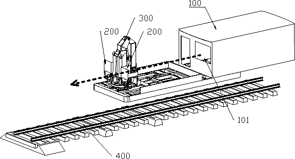
[0067]The first embodiment above provides a specific implementation manner in which the operation cabin 10 moves along the guide rail 2 , so that the operation cabin 10 can move from one side of the mechanical arm 300 to the other side on the base 1 . However, in order to operate the robot arm 300 conveniently, the front side of the operation cabin 10 should face the direction of the robot arm 300 . If the operation cabin 10 is only moved along the guide rail 2 from one side of the robot arm 300 to the other side, there may be a problem that the front side of the operation cabin 10 cannot face the direction of the robot arm.

[0068] In view of the above problems, this embodiment has been improved on the basis of the above-mentioned first implementation. The supporting and rotating mechanism of this embodiment also includes a self-rotating assembly, which is rotatably connected to the support frame 3 and connected to the operating cabin 10. So that the operating cabin 10 can r...


PUM


Abstract

The invention provides a movable operation cabin structure, relates to the technical field of engineering machinery and rail transit, and solves the technical problems that mechanical equipment only has one operation cabin, the visual field of one side is limited in the operation process, and potential safety hazards exist. The movable operation cabin structure comprises a base located on an operation vehicle body, a supporting rotating mechanism and an operation cabin, an operation component is arranged on the base, and a guide rail is arranged on the peripheral wall of the base; and the operation cabin is fixed to the supporting rotating mechanism, the supporting rotating mechanism is movably arranged along the guide rail, and the operation cabin can be driven by the supporting rotating mechanism to rotate from one side of the operation component to the other opposite side of the operation component along the guide rail and is locked with the base. According to the requirements of a construction site, the position of a cab can be rapidly moved at any time, the optimal working view during operation of the mechanical arm and the optimal driving view during driving of an operation vehicle body are achieved, the working efficiency is improved, and the working danger is reduced.

Description

technical field [0001] The invention relates to the technical field of rail transportation, in particular to a mobile operating cabin structure. Background technique [0002] With the advancement of science and technology in our country, various engineering vehicles and mechanical equipment have appeared. see figure 1 as shown, figure 1 It is a schematic diagram of the mechanical arm on the rail work vehicle commonly used in the prior art working on the right side of the track; figure 1 The arrow direction of the middle dotted line represents the line of sight direction of the driver in the equipment operation cabin. The rail work vehicle in the prior art includes a work vehicle body 100 and an operating platform, wherein the operating platform is located at the front of the vehicle body, and the vehicle body 100 is provided with a driver In the room 101, a mechanical arm 300 and an equipment operating cabin 200 are arranged on the operating table. The equipment operating...

Claims


Application Information

Patent Timeline
IPC IPC(8): B61D15/00B25J5/06
CPCB61D15/00B25J5/06
Inventor 王先尧陆园张铮唐宗武陈殿春
Owner 一路行(北京)科技有限公司
Why Eureka
Try Eureka