Oil-electricity hybrid electro-hydraulic numerical control bending machine with deflection compensation structure

A technology for compensation structure and bending machine, which is applied in the direction of using tools for cleaning, cleaning methods and utensils, chemical instruments and methods, etc., can solve the problems of cumbersome operation, difficult and accurate adjustment, time-consuming and laborious, etc., to improve work efficiency. , Improve accuracy and pass rate, avoid cumbersome and imprecise effects

Pending Publication Date: 2022-01-11
南京郎顿机床制造有限公司
View PDF12 Cites 2 Cited by
  • Summary
  • Abstract
  • Description
  • Claims
  • Application Information

AI Technical Summary

Problems solved by technology

[0005] The object of the present invention is to provide an oil-electric hybrid electro-hydraulic numerical control bending machine with a deflection compensation structure, so as to solve the problem that the existing numerical control bending machine needs to manually adjust multiple groups of angles when performing deflection compensation. The operation is cumbersome, time-consuming and labor-intensive, and the adjustment is not easy to be accurate, because it is adjusted separately, it is difficult to adjust to a compensation curve that matches the deformation, which requires high work experience and very skilled operation skills.

Method used


Image

  • Oil-electricity hybrid electro-hydraulic numerical control bending machine with deflection compensation structure
  • Oil-electricity hybrid electro-hydraulic numerical control bending machine with deflection compensation structure
  • Oil-electricity hybrid electro-hydraulic numerical control bending machine with deflection compensation structure

Examples


Embodiment Construction

[0028] The following will clearly and completely describe the technical solutions in the embodiments of the present invention with reference to the accompanying drawings in the embodiments of the present invention. Obviously, the described embodiments are only some, not all, embodiments of the present invention. Based on the embodiments of the present invention, all other embodiments obtained by persons of ordinary skill in the art without making creative efforts belong to the protection scope of the present invention.

[0029] see Figure 1-7 , an embodiment provided by the present invention:

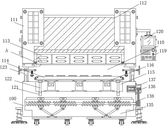
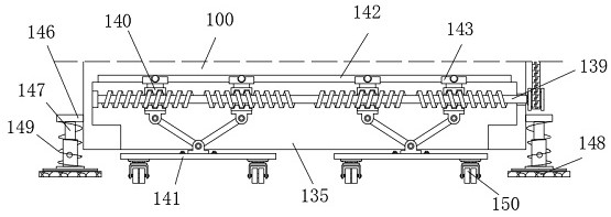
[0030] An oil-electric hybrid electro-hydraulic numerical control bending machine with a deflection compensation structure, including a bending lathe 100, a drive assembly 111 used in this application, a hydraulic cylinder 116, a resistance strain sensor 118, a control panel 119, and a data display 120 and servo motor 137 are all products that can be purchased directly on the market, ...


PUM


Abstract

The invention relates to the technical field of numerical control bending machines, in particular to an oil-electricity hybrid electro-hydraulic numerical control bending machine with a deflection compensation structure, and the oil-electricity hybrid electro-hydraulic numerical control bending machine comprises a bending lathe. According to the oil-electricity hybrid electro-hydraulic numerical control bending machine, a compensation mounting cavity, hydraulic oil cylinders, a mounting base, a resistance strain sensor, a control panel and a data display screen are arranged, so that the hydraulic oil cylinders can drive a bending die base to stretch out and draw back to different degrees according to the requirement of deflection compensation; and the resistance strain sensor senses deformation conditions of all point positions of a bending cutter and the bending die base and transmits signals to the control panel in real time, and the control panel processes information and dynamically sends instructions to all the hydraulic oil cylinders after receiving the signals of the resistance strain sensor. The hydraulic oil cylinders can stretch out and draw back to different degrees according to the requirement of deflection compensation, the working efficiency of the oil-electricity hybrid electro-hydraulic numerical control bending machine is improved, the complexity and inaccuracy of manual debugging are avoided, and the precision and the qualified rate of workpiece machining are improved.

Description

technical field [0001] The invention relates to the technical field of numerically controlled bending machines, in particular to an oil-electric hybrid electro-hydraulic numerically controlled bending machine with a deflection compensation structure. Background technique [0002] The CNC bending machine is a kind of machine equipment that bends the plate on a linear long and narrow mold. Existing CNC bending machines are generally driven by hydraulic pressure, which presses the workpiece through the upper die installed at the bottom of the slider and the lower die installed on the top of the workbench. During the pressing process, the force on the tool and the mold is uneven, the tool will have an upward concave deflection deformation, and the mold will have a downward concave deflection deformation, especially when the bending machine has a large span, this deflection deformation is more obvious. Machining accuracy is greatly affected. [0003] Existing CNC bending machin...

Claims


Application Information

Patent Timeline
Patent Type & Authority Applications(China)
IPC IPC(8): B21D5/02B08B1/00B08B13/00
CPCB21D5/02B21D5/0272B08B13/00B08B1/12
Inventor 吴建海
Owner 南京郎顿机床制造有限公司
Why Eureka
Try Eureka