River energy collection device, manufacturing method and river energy collection method
An energy harvesting and manufacturing method technology, applied in the directions of hydropower, engine components, machines/engines, etc., can solve the problems of low efficiency, little fusion of small bubbles, unavailability of negative pressure of siphon, etc., to achieve high efficiency
- Summary
- Abstract
- Description
- Claims
- Application Information
AI Technical Summary
Problems solved by technology
Method used
Image
Examples
Embodiment 1
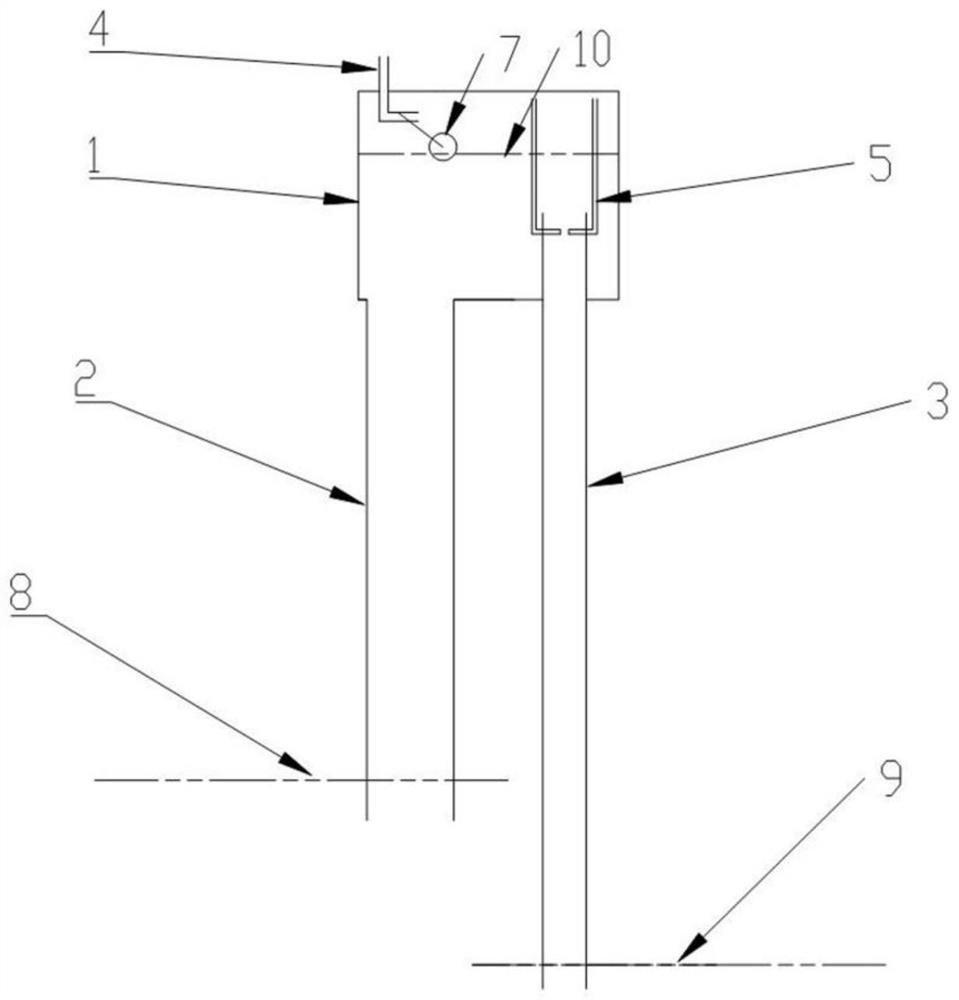
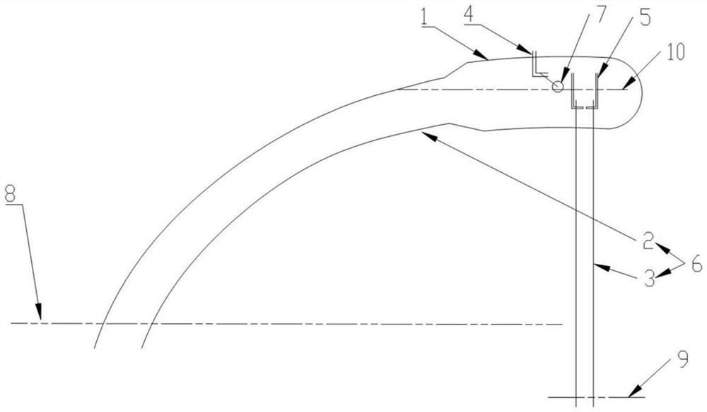
[0136] Such as figure 1 and Figure 4 to Figure 9 As shown, the river energy collection device and manufacturing method of the present invention include: a water storage container 1; an upper water pipe 2, which communicates with the water storage container 1; a lower water pipe 3, which is located in the water storage Below the container 1 and communicated with the water storage container 1; wherein at least the downpipe 3 is at a vertical angle; an air delivery pipe 4, the air delivery pipe 4 is installed in the water storage container 1, and one end of the air delivery pipe 4 It is outside the water storage container 1, and the other end is above the interior of the water storage container 1; at least one gas mixing tube 5 is installed inside the water storage container 1; the gas mixing tube 5 One end is above the water storage container 1 , and the other end is in the downpipe 3 . Wherein the upper water pipe 2 can be set to a vertical angle, or can be set to a non-ver...
Embodiment 11
[0155] Such as Figure 9 As shown, the shapes and structures of the downwater pipe 3 and the air mixing pipe 5 are not limited, and on the basis of Embodiment 1, the outsides of a plurality of air mixing pipes can be set in a connected state.
Embodiment 2
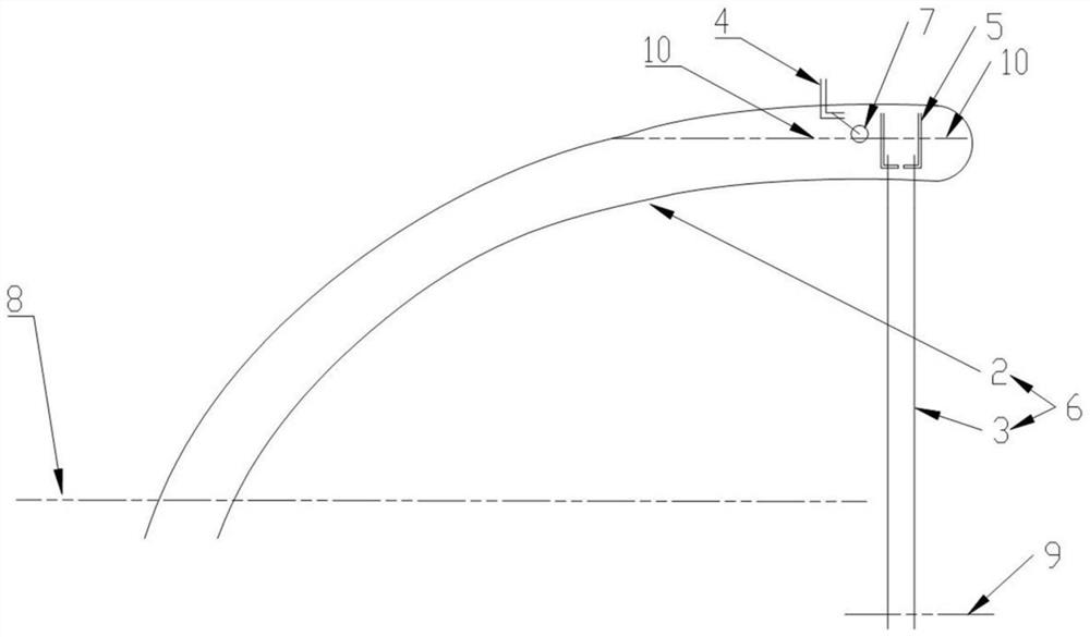
[0157] Such as figure 2 As shown above, for the river energy collection device and manufacturing method of the present invention, the present embodiment 2 can replace the water storage container 1, the upper water pipe 2 and the lower water pipe 3 with the fluid pipe 6 on the basis of the embodiment 1; The fluid pipe 6 includes an upper water pipe 2 and a lower water pipe 3; wherein at least the lower water pipe 3 is at a vertical angle; The outside of the tube 6, the other end is above the inside of the fluid tube 6; at least one gas mixing tube 5, the gas mixing tube 5 is installed in the fluid tube 6; one end of the gas mixing tube 5 is in the fluid tube 6 The other end is inside the fluid pipe 6 and the downpipe 3 mentioned above. On the basis of Embodiment 1, the difference is that by deleting the water storage container 1 described above, in the case of reducing the characteristics of the water storage container 1, it also has the original function, but only The amoun...
PUM
| Property | Measurement | Unit |
|---|---|---|
| Diameter | aaaaa | aaaaa |
| Gap width | aaaaa | aaaaa |
Abstract
Description
Claims
Application Information
 - R&D Engineer
- R&D Manager
- IP Professional
- Industry Leading Data Capabilities
- Powerful AI technology
- Patent DNA Extraction
Browse by: Latest US Patents, China's latest patents, Technical Efficacy Thesaurus, Application Domain, Technology Topic, Popular Technical Reports.
© 2024 PatSnap. All rights reserved.Legal|Privacy policy|Modern Slavery Act Transparency Statement|Sitemap|About US| Contact US: help@patsnap.com


