Sewage treatment device

A sewage treatment device and water treatment technology, applied in the field of water treatment, can solve the problems of inconvenient operation, troublesome maintenance and replacement of the sewage treatment device of the water treatment system, complicated installation and connection, etc.

Pending Publication Date: 2022-01-07
上海威德环保有限公司 +1
View PDF8 Cites 0 Cited by
  • Summary
  • Abstract
  • Description
  • Claims
  • Application Information

AI Technical Summary

Problems solved by technology

The final water treatment system has complex inlet and outlet pipelines and outlet and clean water pipelines. The installation and connection are very complicated and inconvenient to operate. It requires very professional personnel to use a lot of tools to install
Like this, not only can take up more space and artificial material cost, and seriously restrict the popularization of water treatment business
In addition, the maintenance of the water treatment system formed by complex pipelines, such as cleaning pipelines and maintaining and replacing sewage treatment devices, is very troublesome, and personnel without professional training cannot work, which will cause small water treatment projects to be unaffordable. High labor maintenance cost
For example, the structure provided by the CN105163836A patent is also a common structure on the market. When this structure is combined, it is necessary to install additional integrated water inlet pipelines, integrated air intake pipelines, integrated clean water pipelines, and concentrated water integrated pipelines. 4 sets of complex pipelines greatly increase the material cost and installation labor cost, also increase the complexity of on-site installation and increase the risk of improper installation and leakage due to too many interfaces; see the general structure of the final combination of this structure Image 6

Method used


Image

  • Sewage treatment device
  • Sewage treatment device
  • Sewage treatment device

Examples


Embodiment Construction

[0037] Embodiments of the invention are described in detail below, examples of which are illustrated in the accompanying drawings. The embodiments described below by referring to the figures are exemplary and are intended to explain the present invention and should not be construed as limiting the present invention.

[0038] In the description of the present invention, "plurality" means at least two, such as two, three, etc., unless otherwise specifically defined.

[0039] In the present invention, unless otherwise clearly specified and limited, terms such as "installation", "connection", "connection" and "fixation" should be understood in a broad sense, for example, it can be a fixed connection or a detachable connection , or integrated; can be mechanically connected, can also be electrically connected or can communicate with each other; can be directly connected, can also be indirectly connected through an intermediary, can be the internal communication of two components or ...


PUM


Abstract

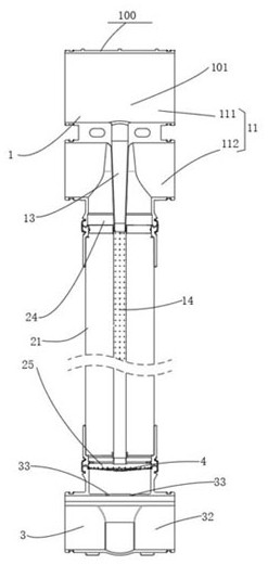
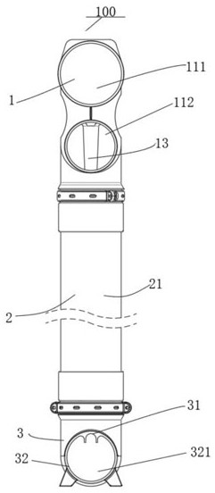
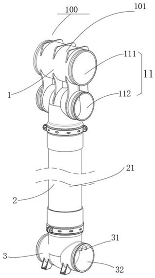
The invention discloses a sewage treatment device which comprises at least one group of water treatment pipe units, and each water treatment pipe unit comprises a treatment pipe assembly, a water inlet pipe assembly and a water outlet pipe assembly. A water treatment cavity is formed in the treatment pipe assembly, and the treatment pipe assembly is provided with a water outlet and a water inlet which are communicated with the water treatment cavity. The water inlet pipe assembly is communicated with the water inlet to guide water in. The water outlet pipe assembly comprises a water outlet pipe fitting and a flow guide pipe. A clear water cavity and a concentrated water cavity are formed in the water outlet pipe fitting, and the clear water cavity communicates with the water outlet to guide out clear water. One end of the flow guide pipe is communicated with the concentrated water cavity, the other end of the flow guide pipe penetrates through the clear water cavity and the water outlet and extends into the water treatment cavity to guide out the concentrated water. The sewage treatment device disclosed by the invention is easy to mount and combine, convenient for backwashing self-cleaning water treatment and small in occupied space.

Description

technical field [0001] The invention relates to the field of water treatment, in particular to a sewage treatment device. Background technique [0002] The pipeline structure of the common sewage treatment device on the market is usually to set the intake pipe, the water inlet pipe, the water outlet pipe and the clear water pipe on it, and then connect each kind of pipeline through complicated branch pipelines outside the sewage treatment device. Connect them separately, and finally connect all the sewage treatment devices together to form a water treatment system. The final water treatment system has complex inlet and outlet pipelines and outlet and clean water pipelines. The installation and connection are very complicated and inconvenient to operate. It requires very professional personnel to use a large number of tools to install. Like this, not only can take up more space and artificial material cost, and seriously restrict the popularization of water treatment busines...

Claims


Application Information

Patent Timeline
IPC IPC(8): C02F3/02C02F3/34
CPCC02F3/02C02F3/34C02F2203/006Y02W10/10
Inventor 姚志华陆雪松张显超
Owner 上海威德环保有限公司
Why Eureka
Try Eureka