A high-efficiency power station for new energy special vehicles

A technology for special vehicles and power stations, which is applied in charging stations, power management, electric vehicles, etc. It can solve problems such as poor positioning effect, easy vehicle jumping out, and increasing the accelerator.

Active Publication Date: 2022-04-29
济南萨博特种汽车有限公司
View PDF12 Cites 0 Cited by
  • Summary
  • Abstract
  • Description
  • Claims
  • Application Information

AI Technical Summary

Problems solved by technology

[0002] Battery swapping is a way to quickly replenish energy for electric vehicles. Specifically, it refers to removing the power battery of the car through the battery swapping equipment and immediately replacing another set of power batteries; One of the main challenges of battery replacement technology is the positioning of battery replacement equipment, vehicles, and batteries; this is because: after the positioning is completed, the battery replacement equipment can perform battery replacement operations and complete the separation and installation of batteries and vehicles, that is, to The fastening device connected between the battery and the car completes the locking and unlocking operations; the position where each car enters the battery swap station is not consistent, and the battery swapping equipment needs to be able to deal with this uncertainty; when positioning the vehicle’s driving direction, V-shaped grooves are usually set so that the wheels are located in the middle of the V-shaped grooves, and the direction of the vehicle is positioned. When the V-shaped grooves are shallow, the positioning effect is poor, and the wheels are easy to roll out of the V-shaped grooves, and the driving direction of the vehicle cannot be determined. If the V-shaped groove is deep, it is difficult for the wheels to drive out after entering the V-shaped groove, and the accelerator needs to be increased, which will cause the vehicle to jump out easily, and there is a driving risk, which cannot meet the actual needs, so we invented a new energy High-efficiency power station for special vehicles

Method used


Image

  • A high-efficiency power station for new energy special vehicles
  • A high-efficiency power station for new energy special vehicles
  • A high-efficiency power station for new energy special vehicles

Examples


Embodiment Construction

[0012] In order to make the purpose, technical solutions and advantages of the embodiments of the present invention clearer, the technical solutions in the embodiments of the present invention will be clearly and completely described below in conjunction with the drawings in the embodiments of the present invention. Obviously, the described embodiments It is a part of embodiments of the present invention, but not all embodiments. Based on the embodiments of the present invention, all other embodiments obtained by persons of ordinary skill in the art without creative efforts fall within the protection scope of the present invention.

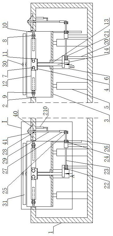
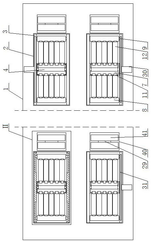
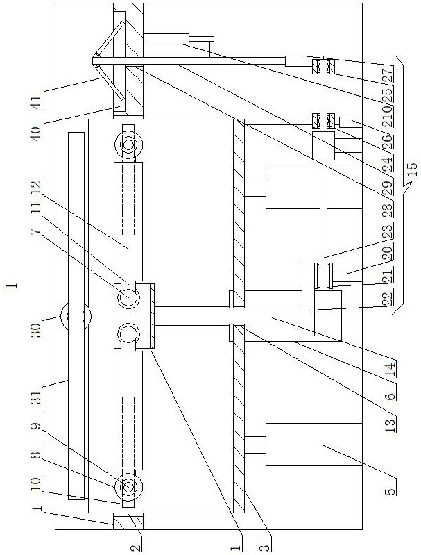
[0013] A high-efficiency replacement station for new energy special vehicles, as shown in the figure, includes a box body 1, and the four corners of the top side of the box body 1 are respectively provided with rectangular through-slots 2, and the first inverted U-shaped plate 3 is movably installed in the rectangular through-slot 2, and the second...


PUM


Abstract

A high-efficiency replacement station for new energy special vehicles, including a box body, rectangular through-slots are respectively provided at the four corners of the top side of the box body, a first inverted U-shaped plate is movably installed in the rectangular trough, and a second inverted U-shaped plate is movably installed in the first inverted U-shaped plate. Inverted U-shaped plate, the first inverted U-shaped plate is connected to the box body through several first electric push rods, the first inverted U-shaped plate and the second inverted U-shaped plate are connected through several first spring rods, and the second inverted U-shaped plate is connected through several first spring rods. The two first horizontal shafts are rotated and installed in the two inverted U-shaped plates, and the opposite side of the two first horizontal shafts is provided with a second horizontal shaft. The other end of the first inverted U-shaped plate is slidingly fitted and connected. The invention has a simple structure and ingenious concept. Through the V-shaped roller structure that can adjust the angle, even if the wheel passes through the corresponding V-shaped roller structure, the V-shaped roller structure can be used to position and fix the wheel, and the gravity of the vehicle itself can be used to Adjusting the angle of the V-shaped roller structure can meet market demand and is suitable for promotion.

Description

technical field [0001] The invention belongs to the field of battery swapping devices for power swapping stations, in particular to a high-efficiency swapping station for new energy special vehicles. Background technique [0002] Battery swapping is a way to quickly replenish energy for electric vehicles. Specifically, it refers to removing the power battery of the car through the battery swapping device and immediately replacing another set of power batteries; One of the main challenges of battery replacement technology is the positioning of battery replacement equipment, vehicles, and batteries; this is because: after the positioning is completed, the battery replacement equipment can perform battery replacement operations and complete the separation and installation of batteries and vehicles, that is, to The fastening device connected between the battery and the car completes the locking and unlocking operations; the position where each car enters the battery swap station...

Claims


Application Information

Patent Timeline
Patent Type & Authority Patents(China)
IPC IPC(8): B60L53/80
CPCB60L53/80Y02T10/70Y02T10/72Y02T10/7072
Inventor 李学伟李敏敏梁峰郭晓光赵建泉耿忠亮王延伟王鑫李小清卢浩崔涛
Owner 济南萨博特种汽车有限公司
Why Eureka
Try Eureka